Rockwell Automation Publication 440R-UM013G-EN-P - December 2022 31
Chapter 4
Configuration
Introduction The multi-position, rotary switches on the front face of a GSR safety relay determine its
functionality. The configuration method of a GSR safety relay must provide means to help
protect against manipulation and maintain the integrity of the configuration.
The rotary switches accommodate a small screwdriver to turn the switch to the desired switch
position. The configuration procedure implies a willing action by the person who configures
the safety function to prove that the person is conscious and able to perform this task.
Therefore, GSR safety relays require a procedure of turning a switch to position [0] to start the
Configuration mode and then turn to the position desired.
The status indicators on the front panel provide continuous feedback by flashing the switch
positions. Power cycling the device completes the Configuration mode and the device enters
operation.
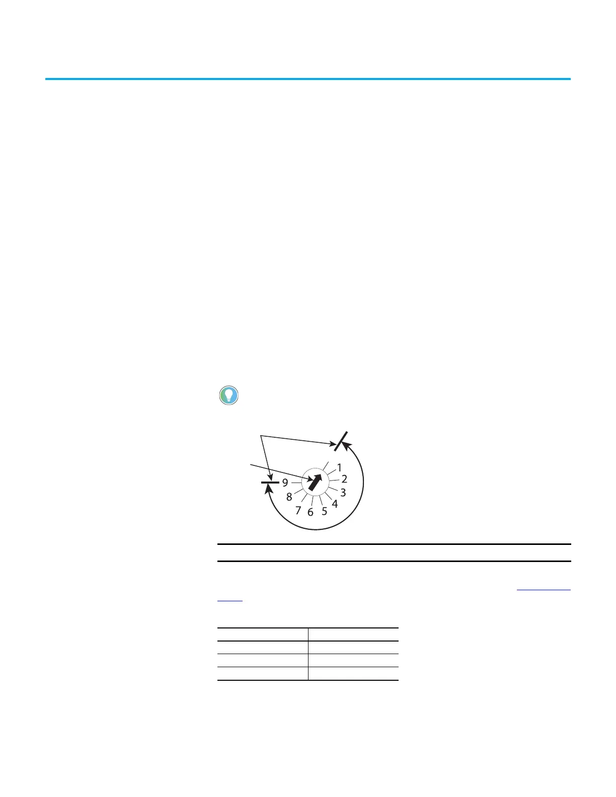
Switch Adjustment These safety relays have multi-position switches on their front face. Use a small screwdriver
to set the switches to the desired setting.
Figure 26 - Configuration Switch Adjustment
CI and SI safety relays have a three-position Reset switch. This switch determines whether the
safety relay uses a monitored manual reset or an automatic/manual switch (see Definitions
on
page 8).
Make note of the mechanical stop location.
IMPORTANT Adjust the switches gently and do not turn past the mechanical stops.
Table 6 - CI and SI Safety Relay Logic Switch
Position Function
0 Start configuration
MM Monitored manual reset
AM Automatic/manual reset
Mechanical
Stops
Screwdriver
Slot

 Loading...


