Rockwell Automation Publication 440R-UM013G-EN-P - December 2022 21
Chapter 3 Power, Ground, and Wire
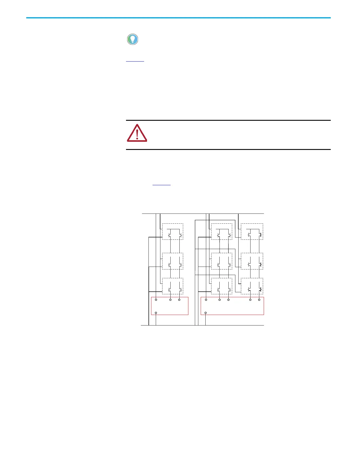
Figure 11 shows an example of a wiring configuration that includes non-cascadable and
cascadable devices. The non-cascadable devices (Devices 1 and 2) must always start the
cascade. Many cascadable devices (Devices 3…6 or more) can be included in the input circuit.
All devices must have the same voltage supply reference (for instance, 24V Com) as the safety
relay.
Examples of non-cascadable devices include GuardShield safety light curtains, SafeZone laser
scanners, and safety sensors. Examples of cascadable devices include SensaGuard interlock
switches, and the TLS-ZR and 440G-LZ guard locking interlock switches.
Place devices with electromechanical (EM) outputs after the non-cascadable device. You can
place the EM safety relay devices anywhere in the chain after the first OSSD device.
From the perspective of the GSR safety relay, only the OSSD device closest to the safety relay
(Device 3 in Figure 11
) is of concern. The other devices with OSSD outputs do not affect the
performance of the safety relay. The EM safety relay devices can suffer from masked faults,
their safety rating is limited to Category 3 per ISO13849-1.
Figure 11 - Example Connections to Device with Cascaded and Non-cascaded OSSD Devices
GSR safety relays cannot detect short circuits of the OSSD device outputs. The PWR/Fault
status indicator of your GSR safety relay remains steady green. The device with the OSSD
outputs must detect short circuits of its own OSSD outputs. When detected, the device must
shut off both OSSD outputs and go to a faulted state. A status indicator must inform you that
the OSSD is faulted.
Safety Mats
Guardmaster® (and similar) safety mats can connect to safety relays. These safety mats use
parallel metal-plate technology. Stepping on the safety mat shorts the top metal plate to the
bottom metal plate. With the proper connections, safety relays detect the presence of an
object on the safety mat and turn off their outputs. With no presence on the safety mat, safety
relays turn on their outputs.
• OSSD1 can connect to either S12 or S22 and OSSD2 can connect to either S12 or S22.
• The safeguarding devices must have the same voltage supply reference (24V Com)
as the safety relay.
ATTENTION: You must consider the cumulative response time of all
cascaded devices, the safety relay, and output devices to verify that the
safety function is fulfilled within the required time that the risk assessment
determines.
A2
S12
A1
A2
A1
A2
S22 S32 S42A1
A2
A1 S12 S22
+24V DC
24V Com
A1
A2
A1
A2
A1
A2
A1
A2
A1
A2
A1
A2
A1
A2
Device 1
Input 1 Input 1 Input 2
CI and SI
DI and DIS
Device 3
Device 5
Device 1
Device 3
Device 5
Device 2
Device 4
Device 6

 Loading...


