Rockwell Automation Publication 440R-UM013G-EN-P - December 2022 27
Chapter 3 Power, Ground, and Wire
Reset and Monitor Input The CI, DI, DIS, and SI safety relays have a reset/monitoring input (terminal S34). The
expansion safety relays (EM and EMD) do not have a reset input.
You can configure the reset action for either automatic or manual reset. When the safety relay
is configured for automatic reset, the safety relay outputs turn on as soon as the safety inputs
are closed if terminal 34 is connected to 24V. If a normally open switch is placed in the circuit,
the reset function occurs on the leading edge (when the switch is pressed).
When the safety relay is configured for manual reset, the safety relay outputs turn on after the
inputs are closed and then the reset input is cycled from off to on and then back off again.
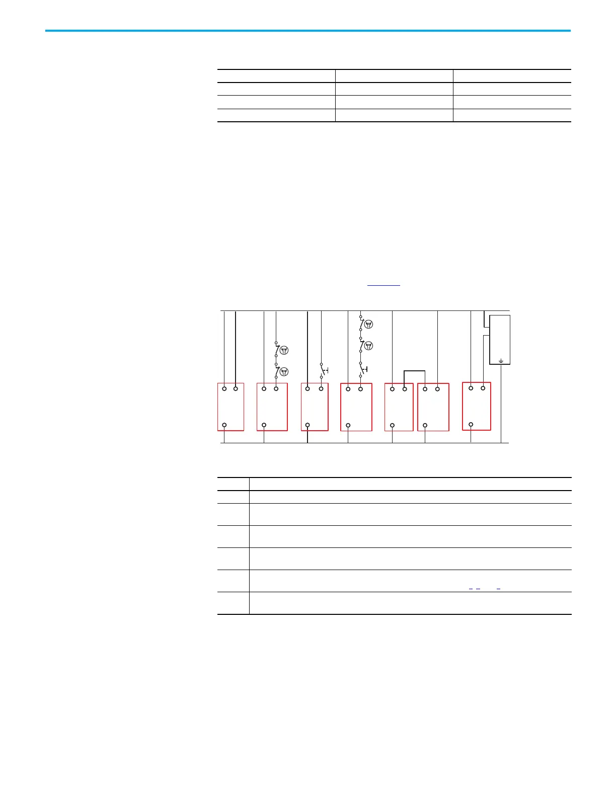
Monitor external devices, like safety control relays and safety contactors, by adding N.C.
contacts in series with the reset signal. Figure 21
shows typical reset/monitoring circuits.
Figure 21 - Typical Reset/Monitoring Circuits
Automatic/Manual Reset
Use automatic reset when the risk assessment does not require additional manual
intervention to reset the safety system. Automatic reset is often used with partial body access
or where an additional control is implemented in the machine control system to start the
hazardous portion of the machine after the safety inputs are closed.
Table 4 - Auxiliary Outputs
Safety Relay Type of Output Terminal Connections
CI Electromechanical 41/42
DI, DIS, SI Transistor Y32
EM, EMD Transistor X32
Circuit Description
1 In automatic/manual reset, you can make a direct connection to 24V DC.
2
Output devices are monitored with their normally closed contacts. Only use this circuit in automatic/
manual reset.
3
An N.O push button is used. You can configure the safety relay for automatic/manual reset or monitored
manual reset.
4
Output devices are monitored along with an N.O. push button. You can configure the safety relay for
automatic/manual reset or monitored manual reset.
5
An EM or EMD expansion safety relay is used to supply the voltage to terminal S34. This circuit can also
contain feedback contacts and a Reset push button, similar to circuits 2
, 3, and 4.
6
A PLC is used to generate the reset signal. You can configure the GSR safety relay for either automatic/
manual or monitored manual reset.
+24V DC
24V DC Com
S34A1
A2
12
34 5 6
S34A1
A2
S34A1
A2
S34A1
A2
+
1
2
3
PLC
S34A1
A2
S34A1
A2
A1
A2
Circuit
Circuit Circuit Circuit Circuit Circuit
EM or
EMD

 Loading...


