40 Rockwell Automation Publication 440R-UM013G-EN-P - December 2022
Chapter 7 EMD Safety Relay Timing Functions
Case 3
10. The logic link signal at terminal L12 turns on, and the safety outputs turn on within the
specified reaction time.
11. The logic link signal turns off and the off-delay timer starts.
12. During off-delay time, the logic link signal turns off. A recoverable fault occurs. The
PWR/Fault status indicator is green and flashing red four times.
13. The logic link turns back off. The fault continues to exist.
14. The off-delay time has elapsed; the safety outputs turn off; and the fault is
automatically cleared.
Off Delay, Retriggerable To use the retriggerable off-delay function, input terminal B1 must connect to terminal B2
before the configuration process. The off-delay timer starts when the logic link signal at
terminal L12 turns off. During the timing cycle, the off-delay timer is automatically reset to
zero when the logic link turns back on. Figure 34
shows two cases of the timing sequences
that can occur with this configuration.
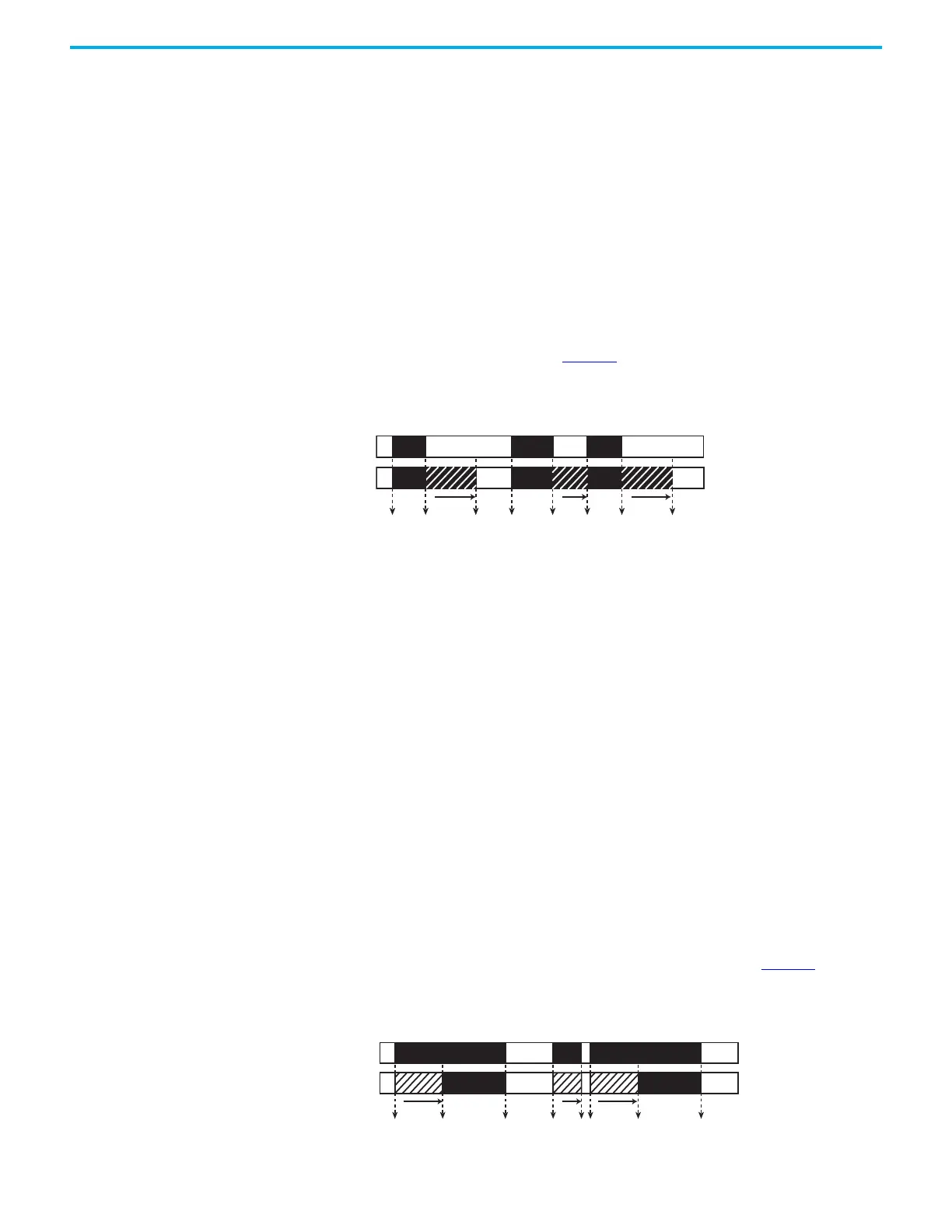
Figure 34 - Off-delay, Retriggerable Timing Diagram
Case 1
1. The logic link signal at terminal L12 turns on, and the safety outputs turn on
immediately (that is, within the specified reaction time).
2. The logic link signal turns off, and the off-delay timer starts.
3. The off-delay time has elapsed, and the safety outputs turn off.
Case 2
4. The logic link signal at terminal L12 turns on, and the safety outputs turn on within the
specified reaction time.
5. The logic link signal turns off, and the off-delay timer starts.
6. During off-delay time, the logic link signal turns on. The off-delay timer is set back to
zero, and the safety outputs remain on. No fault occurs.
7. The logic link signal turns off, and the off-delay timer starts.
8. The off-delay time has elapsed, and the safety outputs turn off.
On Delay To use the on-delay function, terminal B1 must be an open connection. The on-delay timer
starts when the logic link signal at terminal L12 turns on. The safety outputs turn on after the
delay time expires and remain on until the logic link signal turns off. If the logic link signal
turns off during the timing cycle, the safety outputs turn off immediately. Figure 35
shows two
cases of the timing sequences that can occur with this configuration.
Figure 35 - On-delay Timing Diagram
t t t
12 34 567 8
Case 1 Case 2
L12
Safety
Output
t t
12 34567 8
t
Case 1 Case 2
L12
Safety
Output

 Loading...


