74 Rockwell Automation Publication 440R-UM013G-EN-P - December 2022
Chapter 11 Troubleshooting
Figure 89 - Measure X32 Voltage
EMD Expansion Safety Relay
B1/B2 Inputs (Step 7)
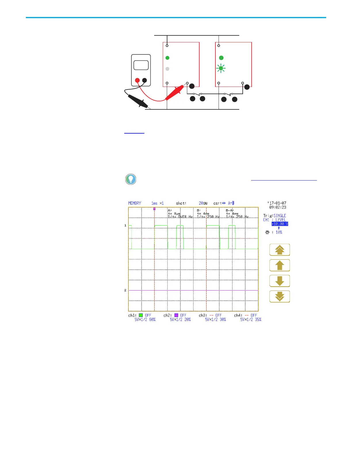
Figure 90 shows the waveform from B1 to B2. This waveform is the same as the single wire
safety waveform. The waveform is present only when the output of the EMD expansion safety
relay is on. With a digital multimeter, the voltage measures 8…9V DC.
If the B1 status indicator is on, but no voltage is read, the expansion safety relay must be
replaced.
Figure 90 - The B1-B2 Waveform When the EMD Safety Relay Output is On
X32A2 A2
A1 A1
23
S34
Volts
DMM
+24V DC
0V
1
2 3
4 5
PWR/Fault
OUT
PWR/Fault
OUT
6
CI, DI, DIS, or SI
EM or EMD
For more information on retriggerable inputs, see Retriggerable Input on page 29.

 Loading...


