20 Rockwell Automation Publication 440R-UM013G-EN-P - December 2022
Chapter 3 Power, Ground, and Wire
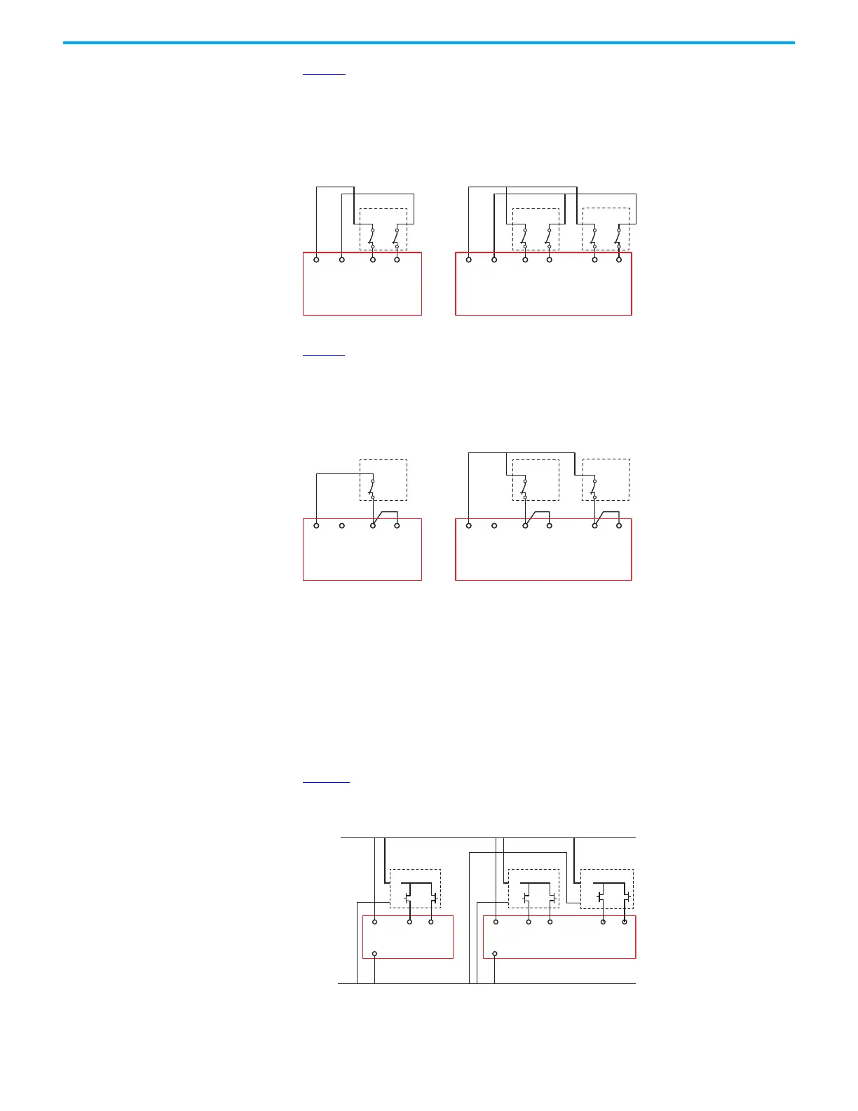
Figure 8 shows the typical connections for devices with 2 N.C. mechanical contacts. One side
of each contact is connected to a pulse-testing outputs S11 and S21. The other side is
connected to an input terminal. The CI and SI safety relays have one set of input terminals. The
DI and DIS safety relays have two sets of input terminals. The DI and DIS safety relays can
operate with only one device that is connected to either input or with devices that are
connected to both inputs.
Figure 8 - Example Connections to 2 N.C. Mechanical Contacts
Figure 9 shows the typical connections for devices with 1 N.C. mechanical contact. One side of
the contact is connected to a pulse-testing output S11. The other side is connected to two input
terminals. The CI and SI safety relays only have one set of input terminals. The DI and DIS
safety relays have two sets of input terminals. The DI and DIS safety relays can operate with
only one device that is connected or with devices that are connected to both inputs.
Figure 9 - Example Connections to 1 N.C. Mechanical Contact
Devices with OSSD Output
Devices, such as the GuardShield™ safety light curtains, SafeZone™ laser scanners,
SensaGuard™ interlock switch, TLS-Z and 440G-LZ guard locking switches, and Bulletin 442G
Multifunction Access Box (MAB), have current-sourcing PNP semiconductor outputs (OSSD).
Devices with OSSD send their own pulse-tested safety signals through their outputs. These
devices do not need to connect to the safety relay pulse-testing outputs. These devices must
have a common power supply reference (24V Com).
Figure 10
shows a typical example of the connections for devices, like safety light curtains or
laser scanners, with non-cascadable OSSD outputs.
Figure 10 - Example Connections to Devices with Non-cascadable OSSD Outputs
S11 S21 S12 S22 S32 S42S11 S21 S12 S22
Device 1
Device 1
Device 2
Input 1 Input 1 Input 2
Pulse
Testing
Outputs
Pulse
Testing
Outputs
CI and SI
DI and DIS
S11 S21 S12 S22 S32 S42S11 S21 S12 S22
Device 1
Device 1
Device 2
Input 1
Input 1 Input 2
Pulse
Testing
Outputs
Pulse
Testing
Outputs
CI and SI
DI and DIS
S12
A2
A1
A2
S22 S32 S42
A1
A2
A1A1 S12 S22
A2
+24V DC
24V Com
A1
A2
Device 1 Device 1
Device 2
Input 1
Input 1 Input 2
CI and SI
DI and DIS

 Loading...


