Rockwell Automation Publication 440R-UM013G-EN-P - December 2022 9
Chapter 1
Overview
The Guardmaster® safety relay (GSR) family is a group of advanced general-purpose and
special-purpose safety relays. This user manual addresses the CI, DI, DIS, EM, EMD, and SI
safety relays from this family of relays.
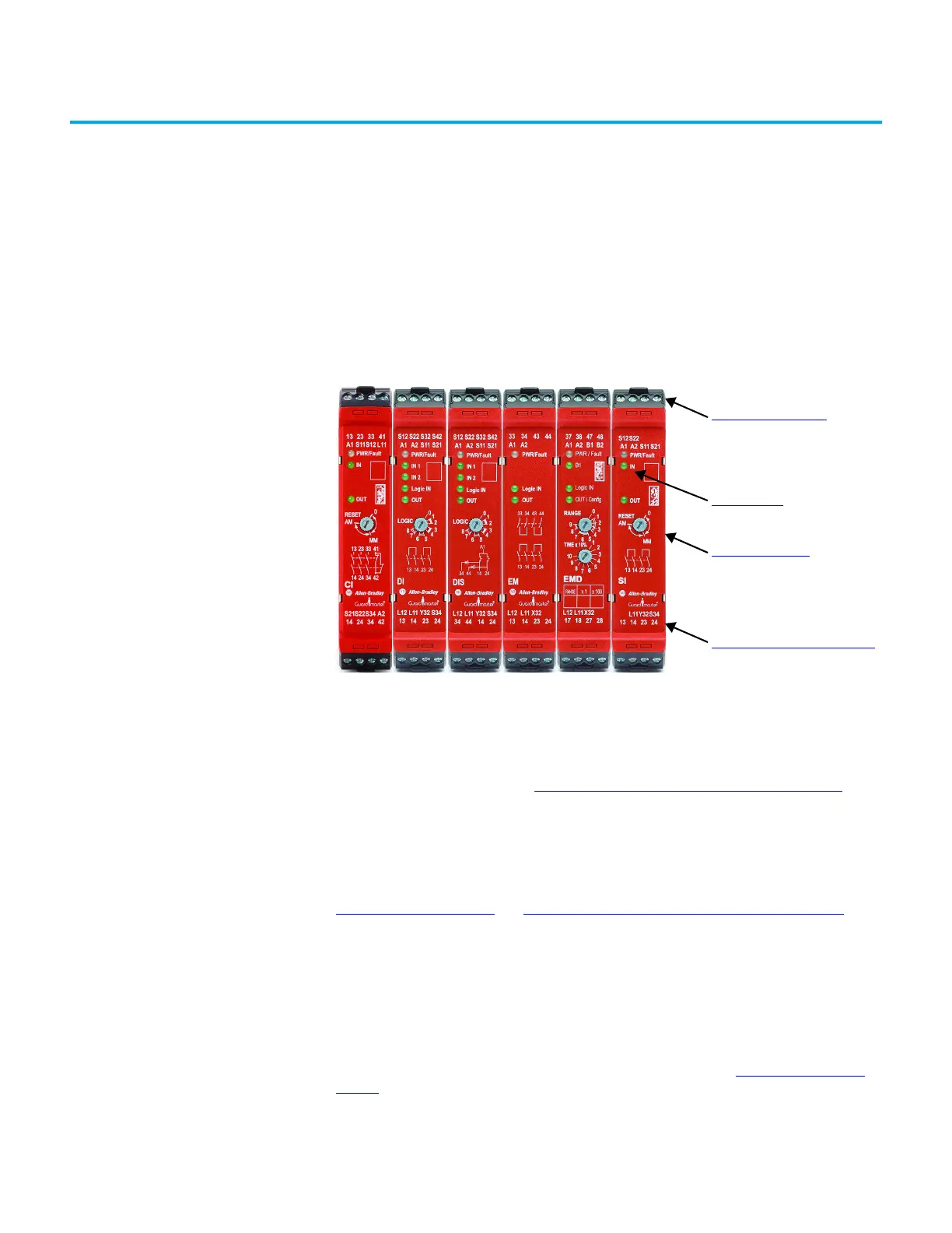
Hardware Features Figure 1 - Safety Relays
Removable Terminal Blocks
Each safety relay module is only 22.5 mm (0.9 in.) wide with four removable terminal blocks
(two on top and two on bottom). The terminal blocks are keyed to confirm that they are
installed in their proper slots. See Terminal Block Removal and Replacement
on page 75.
Status Indicators
Multiple status indicators provide status and diagnostics. Under fault conditions, the PWR/
Fault status indicator flashes in specific patterns to help diagnose the fault. See
Status Indicators
on page 9 and View the PWR/Fault Status Indicator (Step 1) on page 54 for
more information.
Multi-position Switches
Most safety relays are configured by adjusting multi-position switches to set their
functionality
(a)
. The switches are on the front face of the safety relay so you can see the set
position during, and after, configuration. During the configuration process, status indicators
on the front face of the safety relay confirm the switch settings. See Switch Adjustment
on
page 31 for more information.
(a) The EM safety relay does not require configuration.
Removable Terminal Blocks
Status Indicators
Multi-position Switches to set
functionality
Optical Communication Bus
on page 10

 Loading...


