28 Rockwell Automation Publication 440R-UM013G-EN-P - December 2022
Chapter 3 Power, Ground, and Wire
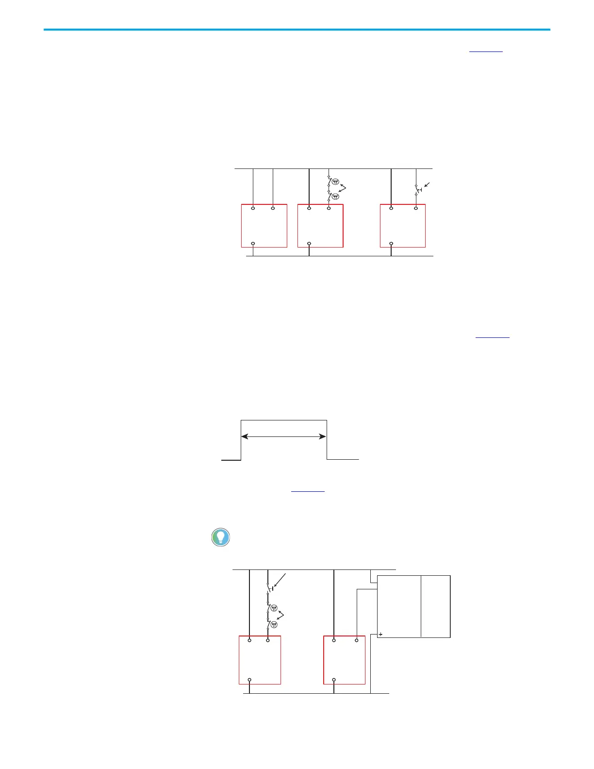
When automatic reset is desired, the S34 input must connect to 24V DC. Figure 22 shows three
possibilities:
a. A direct connection
b. A connection through some monitoring contacts
c. A connection through an N.O. push button.
You can combine the connection through a monitoring contact and push button. When a push
button is used, the reset occurs when the circuit is closed (not when it is released).
Figure 22 - Automatic/Manual Reset Connections
Monitored Reset
Monitored reset requires a specific signal to turn on the safety outputs. The safety inputs and
single wire safety input (if used) must close before the reset. The reset signal must cycle from
0V to 24V and back to 0V within a duration of 250…3000 ms, as shown in Figure 23
. The reset
occurs on the trailing edge. If the reset signal is too short or too long, the reset function is not
executed and you can try again.
Use the monitored reset in applications that have full-body access to the hazard. You can also
use the monitored reset in applications that require partial body access.
Figure 23 - Monitored Reset Signal Duration
You can create the signal with a momentary push button or programmatically create the signal
with a logic controller. Figure 24
shows example wire connections for the reset. The schematic
also shows an example monitoring the mechanically linked, normally closed contacts of two
contactors.
Figure 24 - Monitored Reset Connections
When using a PLC to generate the reset signal, set the duration to 260…2990 ms
for a more reliable reset.
+24V DC
24V DC Com
S34A1
A2
(a) (b) (c)
S34A1
A2
S34A1
A2
CI, DI, DIS,
or SI
CI, DI, DIS,
or SI
CI, DI, DIS,
or SI
Contactor
Monitoring
Momentary Push
Button (N.O.)
+24V DC
24V DC Com
+
1
2
3
1756-OB16
1769-OB8
1746-OB4
1734-OB2
1793-OB4
S34
A1
A2
S34
A1
A2
CI, DI, DIS,
or SI
CI, DI, DIS,
or SI
Contactor
Monitoring
Momentary Push
Button (N.O.)
PLC Output
PLC
Processor

 Loading...


