58 Rockwell Automation Publication 440R-UM013G-EN-P - December 2022
Chapter 11 Troubleshooting
Check Safety Device Inputs
(Step 3)
This step only applies to CI, DI, DIS, and SI safety relays. Each safety relay has a status
indicator for its inputs.
Table 15
shows the voltage levels that are viewed on an oscilloscope versus a digital
multimeter.
Check Voltage-free Contacts
Safety devices (for example; interlock switches, E-stops, or cable pull switches) with voltage-
free contacts must be connected to the pulse testing outputs. You can use a digital multimeter
to measure the input levels.
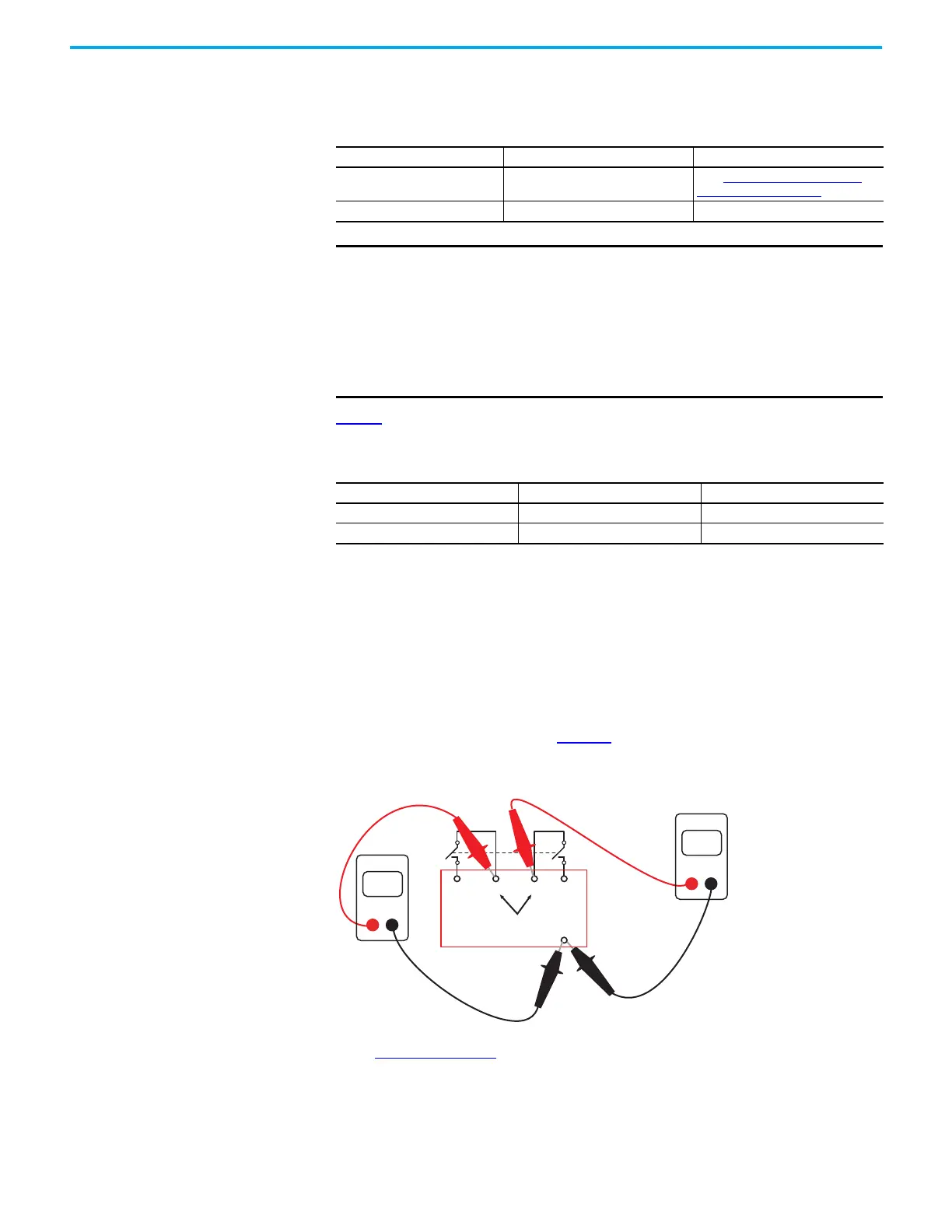
Check CI Safety Relay
1. With the device contacts open, measure the voltage at the pulse testing outputs with a
digital multimeter, as shown in Figure 62. The voltage must be 18…19V on both pulse
testing outputs of the CI safety relay.
Figure 62 - Typical Voltage Measurements of the CI Safety Relay
2. Check the voltage at each of the inputs with the device contacts closed, as shown in
Figure 63 on page 59. The values must be very close to the values measured at
terminals S11 and S21.
a. If both channels are closed, a voltmeter must read about 19V and the IN status
indicator is green. The voltage levels are approximately the same on Channel 1 (S12)
and Channel 2 (S22) because the pulse testing waveforms are similar on both
channels.
Table 14 - Input Status Indicator
IN, IN1, and IN2 Status Indicator Status Action
Green Both channels are closed
Go to Check the Single Wire Safety
Circuit (Step 4) on page 64.
Off One or both input channels are open Continue with this section.
IMPORTANT The following factors affect the value that is measured at the safety
relay inputs:
• Voltage-free contacts
•Pulse testing waveforms
• Capacitance
• Length of wire
• Contact resistance
• Channel sequence
Table 15 - On/Off Voltage
Measurement Device Turn On Voltage Turn Off Voltage
Oscilloscope 11V 5V
Digital Multimeter 6…8V 3…4V
S11 S21S12
19
19
S22
A2
Volts
DMM
Volts
DMM

 Loading...


