Rockwell Automation Publication 440R-UM013G-EN-P - December 2022 71
Chapter 11 Troubleshooting
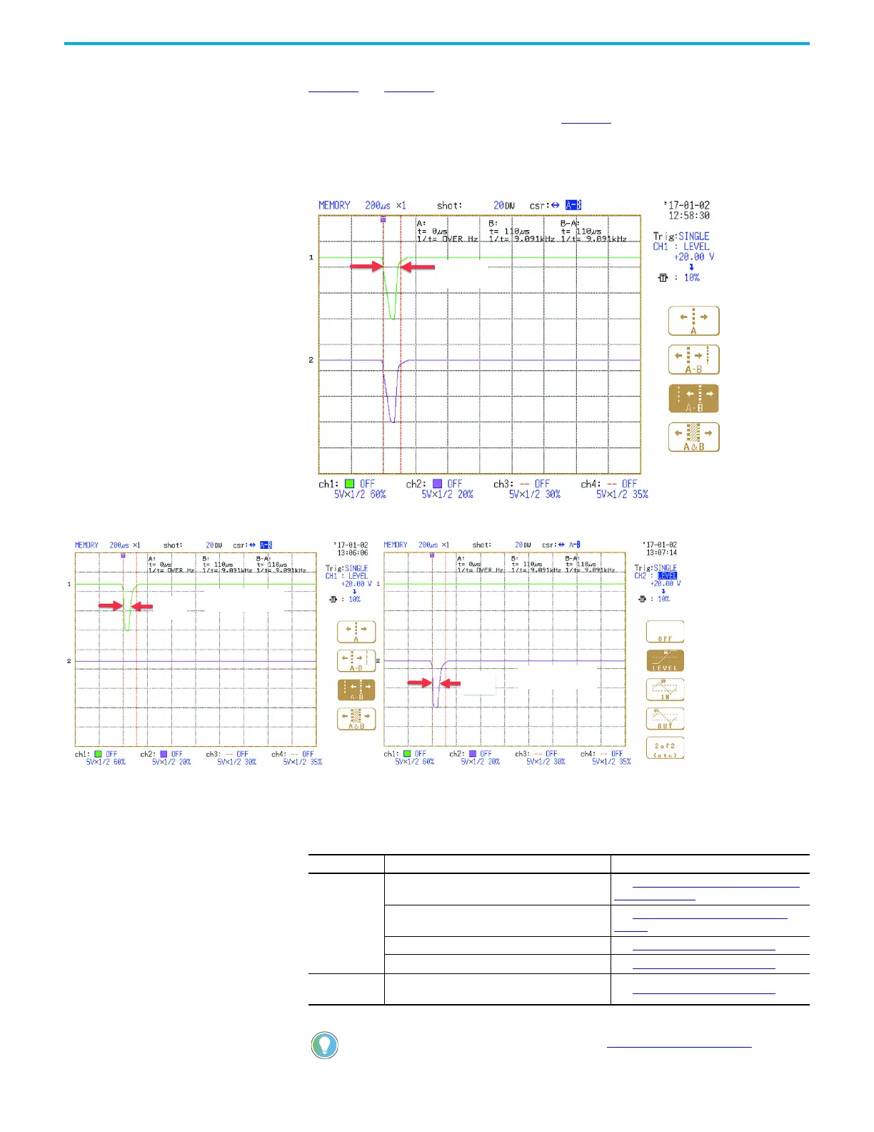
The OSSD test pulses of the DIS safety relay, as viewed by an oscilloscope, are shown in
Figure 84 and Figure 85. Most often, the main transistor triggers the scope; this test pulse
appears on all four terminals simultaneously. The main transistor pulses are about 110 µs wide.
Each channel is tested individually as shown in Figure 85
. The individual pulses are about 50
µs wide. These pulse widths are provided for informational purposes; the pulses cannot be
turned off or adjusted.
Figure 84 - OSSD Main Transistor Test Pulses
Figure 85 - OSSD Channel Transistor Test Pulse
Auxiliary Output Issues
50 µs
50 µs
Terminal 14, 34
Terminal 24, 44
Table 19 - Auxiliary Output Issues
State Symptom Action
OUT status
indicator is off
My PLC does not know that the safety relay is off or
my auxiliary status indicator does not turn on.
See Measure the Auxiliary Output Terminal
Voltage on page 72.
The voltage at terminal 41 is the same as the
supply voltage. However, terminal 42 measures 0V.
See Measure the Contact Resistance
on
page 72.
Terminal Y32 does not turn on. See Check the Y32 Output
on page 73.
Terminal X32 does not turn on. See Check the X32 Output on page 73.
Safety outputs
are off
The Y32 output must be on. This condition is true
for both faulted and running states.
See Check the Y32 Output
on page 73.
For more information on auxiliary outputs, see Auxiliary Output on page 26.

 Loading...


