72 Rockwell Automation Publication 440R-UM013G-EN-P - December 2022
Chapter 11 Troubleshooting
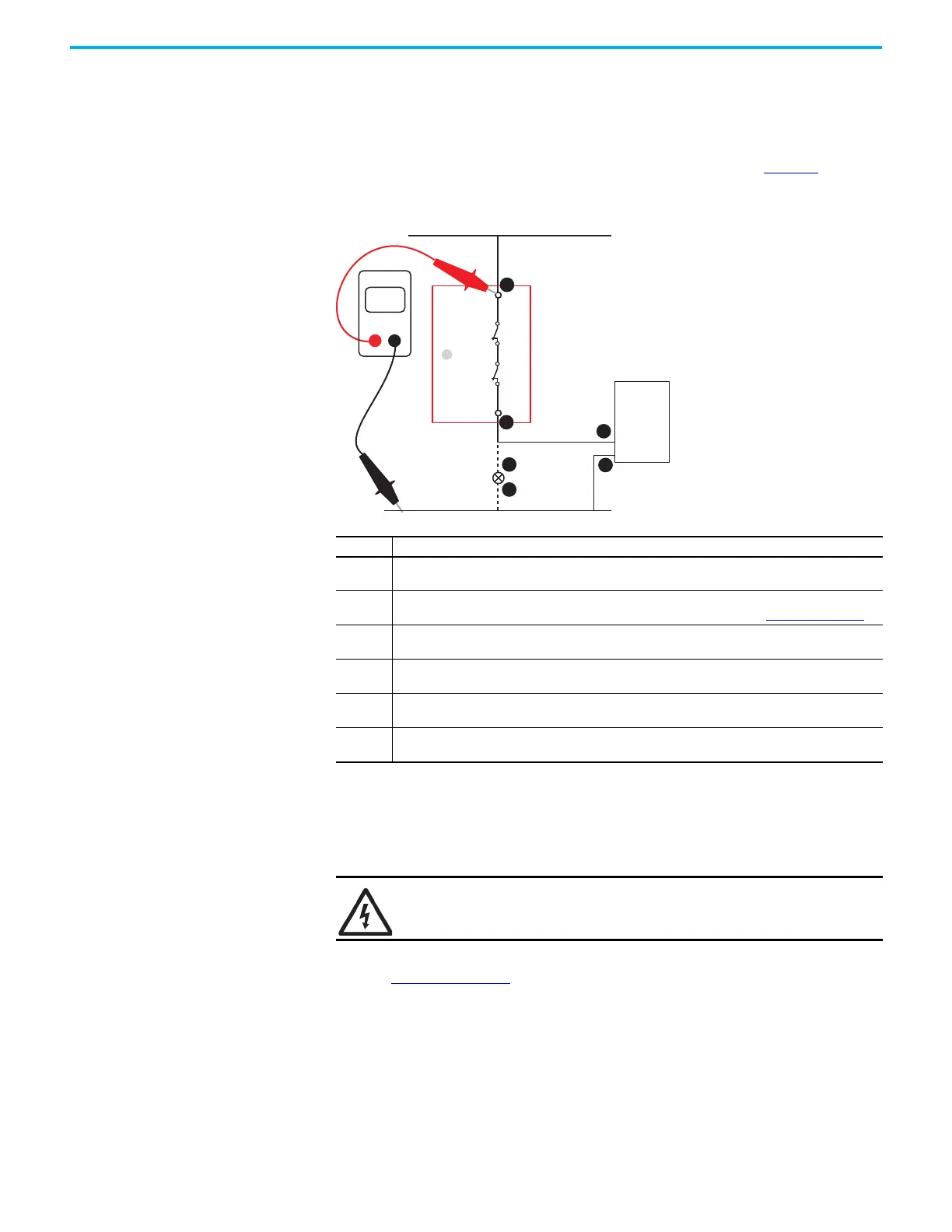
Measure the Auxiliary Output Terminal Voltage
When the OUT status indicator is off, my PLC does not know that the safety relay is off or my
auxiliary status indicator does not turn on.
Confirm that voltage is present at the safety relay terminals and the load. Figure 86
shows an
example of the measurement points for one output channel (41/42).
Figure 86 - Measure Voltage Aux Output Terminals
Measure the Contact Resistance
The OUT status indicator is off, and the voltage at terminal 41 is the same as the supply
voltage. However, terminal 42 measures 0V.
Measure the contact resistance to confirm that the safety relay is not functioning properly. As
shown in Figure 87 on page 73
, remove the power wires to terminal 41 and set the digital
multimeter to ohms. Be sure that the OUT status indicator is off.
The contact resistance must be less than 1 ohm. If it is not, then the internal positive-guided
safety relay is not functioning properly, and the GSR safety relay must be replaced.
Step Description
1
The voltage at 41 must be the same as the supply voltage. If not, check for an open circuit (broken
wire), blown fuse, or tripped circuit breaker.
2
The voltage at 42 must be the same as the supply voltage. If not, the positive-guided safety relay
inside the GSR safety relay is not closing. Measure the contact resistance; see Figure 87 on page 73
.
3
The voltage at the PLC input must be the same as the supply voltage. If not, check for an open circuit
(broken wire), a bad contact at a terminal connection), or go to step 4.
4
Place the black test probe on the PLC common terminal. Verify that the common of the PLC is
connected to the common of the voltage supply.
5
The aux output voltage at one side of the auxiliary status indicator must be the same as the supply
voltage. If not, check for an open circuit (broken wire) between terminal 14 and Aux status indicator.
6
Verify that the aux status indicator is connected to the voltage supply common. The aux status
indicator must be replaced.
SHOCK HAZARD: Turn off power before power connection is removed if +V
supply is greater than 50V.
42
+Vs
41
Volts
DMM
1
2
3
4
5
Com
OUT
6

 Loading...


