Rockwell Automation Publication 440R-UM013G-EN-P - December 2022 41
Chapter 7 EMD Safety Relay Timing Functions
Case 1
1. The logic link signal at terminal L12 turns on, and the on-delay timer starts.
2. The on-delay timer elapses, and the safety outputs turn on.
3. When the logic link signal turns off, the safety outputs turn off.
Case 2
4. The logic link signal at terminal L12 turns on, and the on-delay timer starts.
5. The logic link signal turns off before the on-delay time elapses. The on-delay timer is
reset to zero. No fault occurs.
6. After a brief interruption (even as short as 100 ms), the logic link signal turns back on.
The on-delay timer starts from zero.
7. The on-delay timer elapses, and the safety outputs turn on.
8. When the logic link signal turns off, the safety outputs turn off.
Jog The jog function has two timers: an on-timer and an off-timer. The Range and Time switch
settings set the on-timer during configuration. The on-timer starts when both the B1 terminal
is connected to 24V DC and the logic link signal at terminal L12 is on. The order in which these
two signals turn on is not relevant. When both signals are on, the safety outputs turn on during
the on-timer. After the on-timer expires, the safety outputs turn off and the off-timer starts.
The off-timer is fixed at 500 ms. After the safety outputs turn off, they remain off until the off-
timer elapses. Then the jog can be restarted. Figure 36
shows three cases of timing
sequences.
During the on-timer cycle, the Logic IN status indicator flashes at a 1 Hz rate. During the off-
timer cycle, the Logic IN status indicator flashes at an 8 Hz rate.
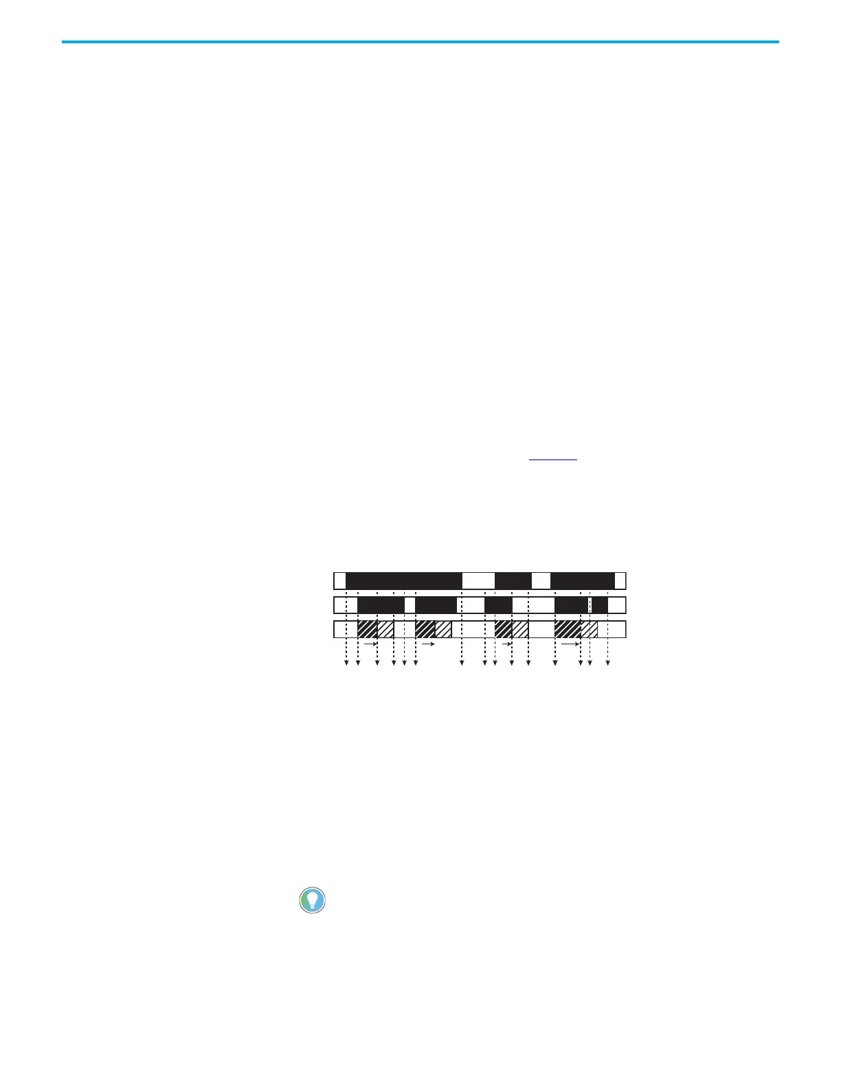
Figure 36 - Jog Timing Diagram
Case 1
1. The logic link signal at terminal L12 turns on.
2. The B1 terminal turns on. The jog on-timer starts, and the safety outputs turn on.
3. The jog on-timer elapses, and the safety outputs turn off. The jog off-timer starts.
4. After 500 ms, the jog function is complete.
5. The B1 inputs turn off.
6. With the logic link input still on, the jog function is repeated when the B1 signal turns on.
7. The logic link signal turns off.
Case 2
8. The B1 signal turns on before the logic link signal.
9. The logic link signal turns on. The jog on-timer starts, and the safety outputs turn on.
The L12 and B1 signals are interchangeable. The B1 signal can remain on and the
L12 turns on and off to execute the jog function.
ttt
12 3 456 7 12 1314 1589 10 11
t
Case 1 Case 2
L12
Safety
Output
B1
Case 3

 Loading...


