46 Rockwell Automation Publication 440R-UM013G-EN-P - December 2022
Chapter 9 Application and Wiring Examples
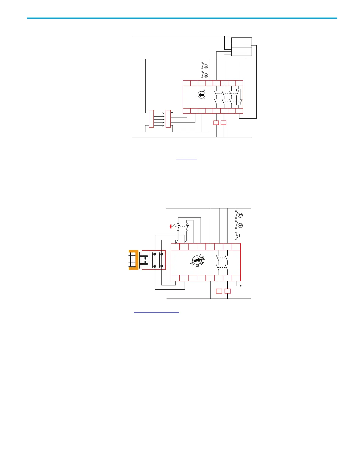
Figure 44 - With Device Using OSSD Outputs, Automatic Reset, AC Load Voltage
DI Safety Relay
(Cat.No.440R-D22R2)
The DI safety relay in Figure 45 monitors two devices having mechanical contacts and is set
for monitored manual reset. With the two devices closed, the operator presses the Reset
button to energize contactors K1 and K2. The DI safety relay verifies that contactors K1 and K2
are off by monitoring the mechanically linked normally closed contacts in the reset circuit.
When the DI safety relay is off, the auxiliary signal at terminal Y32 turns on and reports the
status to a PLC.
Figure 45 - With Two Devices with Mechanical Contacts and Monitored Manual Reset
In Figure 46 on page 47, a DI safety relay monitors a safety mat and non-contact interlock with
OSSD outputs. Make note of the specific wiring for the safety mat. Also, during configuration
and for each power-up, the safety mat must be clear and the interlock closed. The DI safety
relay must be configured for AND logic for the two inputs. The DI safety relay logic setting is 6:
(IN1 AND IN2) OR L12 with automatic reset. The DI safety relay verifies that contactors K1 and K2
are off by monitoring the mechanically linked normally closed contacts in the S34 circuit.
When the DI safety relay is off, the auxiliary signal at terminal Y32 turns on and reports the
status to a PLC. Per ISO 13856-1, safety mat applications require a manual reset function. For
fault detection purposes, all GSR safety relays used for safety mat control must be configured
for monitored manual reset.
S11
S12
S21
S22
S34 A1 13
L11A2 14
23
24
33 41
34 42
CI
440R-S13R2
0
MM
AM
K1
24V DC
L1
120/240V AC
N
24V Com
K2
K1 K2
OSSD1
OSSD2
A1
S11 S21 S12S22
S32 L11 Y32L12
13
14S42
23
24
S34
A2
DI
440R-D22R2
0
1
2
3
4
56
7
8
K1
24V DC
24V Com
K2
K1 K2

 Loading...


