60 Rockwell Automation Publication 440R-UM013G-EN-P - December 2022
Chapter 11 Troubleshooting
Figure 65 - Typical Voltage Measurements of the DI, DIS, and SI Safety Relays with Contacts Closed
3. If a significant difference in voltage levels exists, see Capacitance Effect on page 61
and Long Wire - Resistance Effect
on page 62.
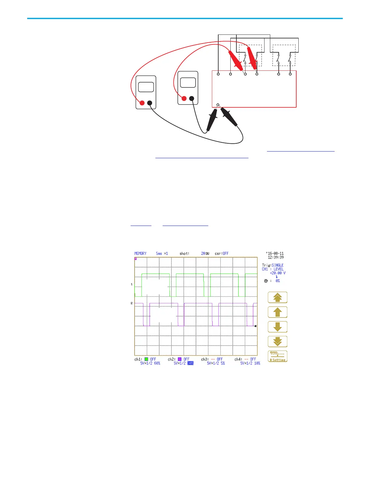
Examine Pulse Test Waveforms
If you have an oscilloscope, you can examine the pulse tests. The test pulses are used to check
for short-circuit conditions; the test pulses are not used to turn the inputs on and off. If they
are clean and square, then they are OK.
The test pulses are generated on terminals S11 and S21. The waveforms, which are shown in
Figure 66
and Figure 67 on page 61, must always be present on their respective safety relays;
the test pulses cannot be turned off or adjusted.
Figure 66 - CI Safety Relay Pulse Test Waveforms
Volts
DMM
Volts
DMM
S11 S21 S12 S22 S32 S42
14
18
A2
Pulse
Testing
Outputs
Device 1 Device 2
Input 1 Input 2
Terminal
S11
Term inal
S21

 Loading...


