32 Rockwell Automation Publication 440R-UM013G-EN-P - December 2022
Chapter 4 Configuration
DI and DIS Safety Relays
The DI and DIS safety relays have a 10-position switch and use only the first nine positions. As
shown in Table 7, this switch configures the safety relay for its reset and logic functionality.
Example 1: Logic setting 1 or 5: If any of the inputs (IN1, IN2, or L12) are on, then the safety relay
refers to the reset logic.
Example 2: Logic setting 4 or 8: If all three of the inputs (IN1, IN2, and L12) are on, then the
safety relay refers to the reset logic.
EMD Safety Relay
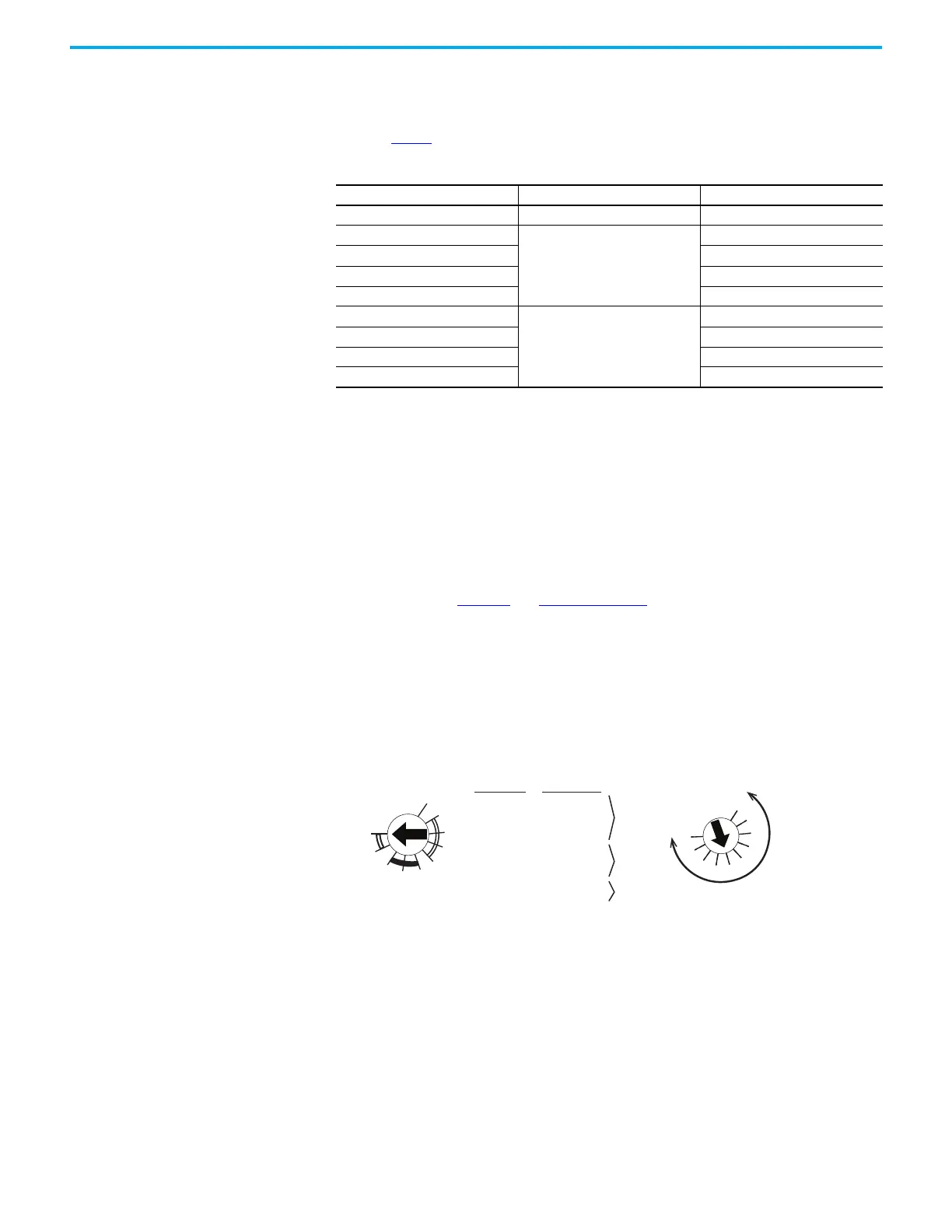
The EMD safety relay has two switches. The combination of the switch settings determines the
functionality and the duration. During configuration, the Time switch determines the duration
of the Range switch. Figure 27 and Table 8 on page 33 show the setting options for the Range
and Time switch.
With the Time switch set to 1 at the start of the configuration process, the duration of the
Range switch is the shorter range.
With the Time switch set to 10 at the start of the configuration process, the duration of the
Range switch is the longer range.
Figure 27 - EMD Safety Relay Range and Time
Table 7 - DI and DIS Safety Relay Logic Switch
Position Reset Function
0 Not applicable Start configuration
1
Monitored manual
(IN1 OR IN2) OR L12
2 (IN1 AND IN2) OR L12
3 (IN1 OR IN2) AND L12
4 (IN1 AND IN2) AND L12
5
Automatic/manual
(IN1 OR IN2) OR L12
6 (IN1 AND IN2) OR L12
7 (IN1 OR IN2) AND L12
8 (IN1 AND IN2) AND L12
1: 10%
2: 20%
3: 30%
4: 40%
5: 50%
6: 60%
7: 70%
8: 80%
9: 90%
10: 100%
5: 0.3...3 s
6: 3...30 s
7: 30...300 s
8: 1...10 s
9: 3...30 s
1: 0.1...1 s
1 10
10...100 s
100...1000 s
300...3000 s
—
—
2: 1...10 s
3: 3...30 s
4: 30...300 s
30...300 s
300...3000 s
100...1000 s
300...3000 s
1
2
3
4
5
67
8
10
9
0
1
2
3
4
5
6
7
8
9
Start Configuration with Time Set to: x 10% or max
RANGE
On
Off
Jog
TIME
TIME
Off-Delay
On-Delay
Jog

 Loading...


