26 Rockwell Automation Publication 440R-UM013G-EN-P - December 2022
Chapter 3 Power, Ground, and Wire
Single Wire Safety Input and
Output
The Single Wire Safety (SWS) feature allows a safety relay to expand the safety function to
additional safety relays using one wire, provided all safety relays have the same voltage supply
reference.
The CI and SI safety relays only have SWS outputs (terminal L11). The DI, DIS, EM, and EMD safety
relays have both SWS inputs (terminal L12) and SWS outputs (terminal L11).
There are many variations and combinations of series and parallel connections of the SWS.
Each L11 terminal (except the EM safety relay) can connect to up to ten L12 terminals. The EM
safety relay simply passes the input SWS signal at L12 directly to its L11 terminal, therefore, it
has no additional fanout capability.
Figure 19
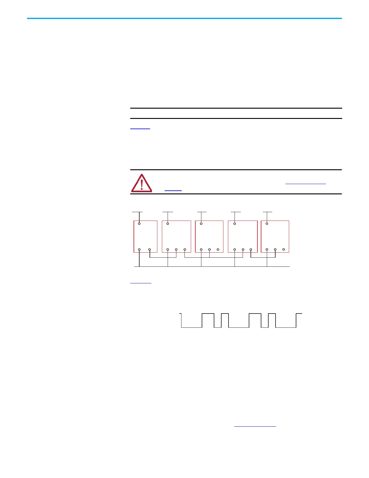
shows an example wiring diagram with SWS input from a DI safety relay and SWS
output connection to an EM safety relay in parallel with a DIS safety relay. The safety relays
must have a common power reference (24V common). In this example, the safety function that
is started by the CI or SI safety relay is expanded to the DI safety relay. The safety functions
monitored by the DI safety relay are expanded to the EM and DIS safety relays. The safety
functions monitored by the DIS safety relay are expanded to the EMD safety relay.
Figure 19 - Example SWS Connections
Figure 20 shows the characteristics of the SWS signal when it is active. It starts with a 1 ms
pulse, followed 700 µs later by a 500 µs pulse. This waveform is repeated every 4 ms. When
inactive, the SWS is 0V.
Figure 20 - SWS Waveform
Auxiliary Output Each safety relay has an auxiliary output. The auxiliary output is not a safety rated output; it is
a low current output that is designed to indicate that the safety output status is off. The
auxiliary output is in the opposite state of the safety outputs. When the safety outputs are on,
the auxiliary output is off. When the safety outputs are off, the auxiliary output is on.
When the EM and EMD safety relays are in a nonrecoverable faulted state, the auxiliary outputs
are in an off state because the auxiliary outputs are often used as the source of the
monitoring circuit. If the EM or EMD safety relays are faulted, the safety system must not reset
until the nonrecoverable fault is corrected.
The DI, DIS, EM, EMD, and SI safety relays have a solid-state transistor auxiliary output. The CI
safety relay has an electromechanical output. Table 4 on page 27
summarizes the terminal
connections of the auxiliary output.
IMPORTANT Do not connect two or more L11 terminals together.
ATTENTION: You must consider the additional response time of each SWS
connection when calculating the safety distance. See Specifications on
page 77 for the response time for each safety relay.
L12 L11
A1
A2
+24V DC +24V DC
L11
A1
A2 L12 L11
A1
A2 L12 L11
A1
A2
+24V DC
SWS SWSSWS
+24V DC
L12 L11
A1
A2
+24V DC
24V DC Com (must have common reference)
CI or SI DI EM DIS EMD

 Loading...


