66 Rockwell Automation Publication 440R-UM013G-EN-P - December 2022
Chapter 11 Troubleshooting
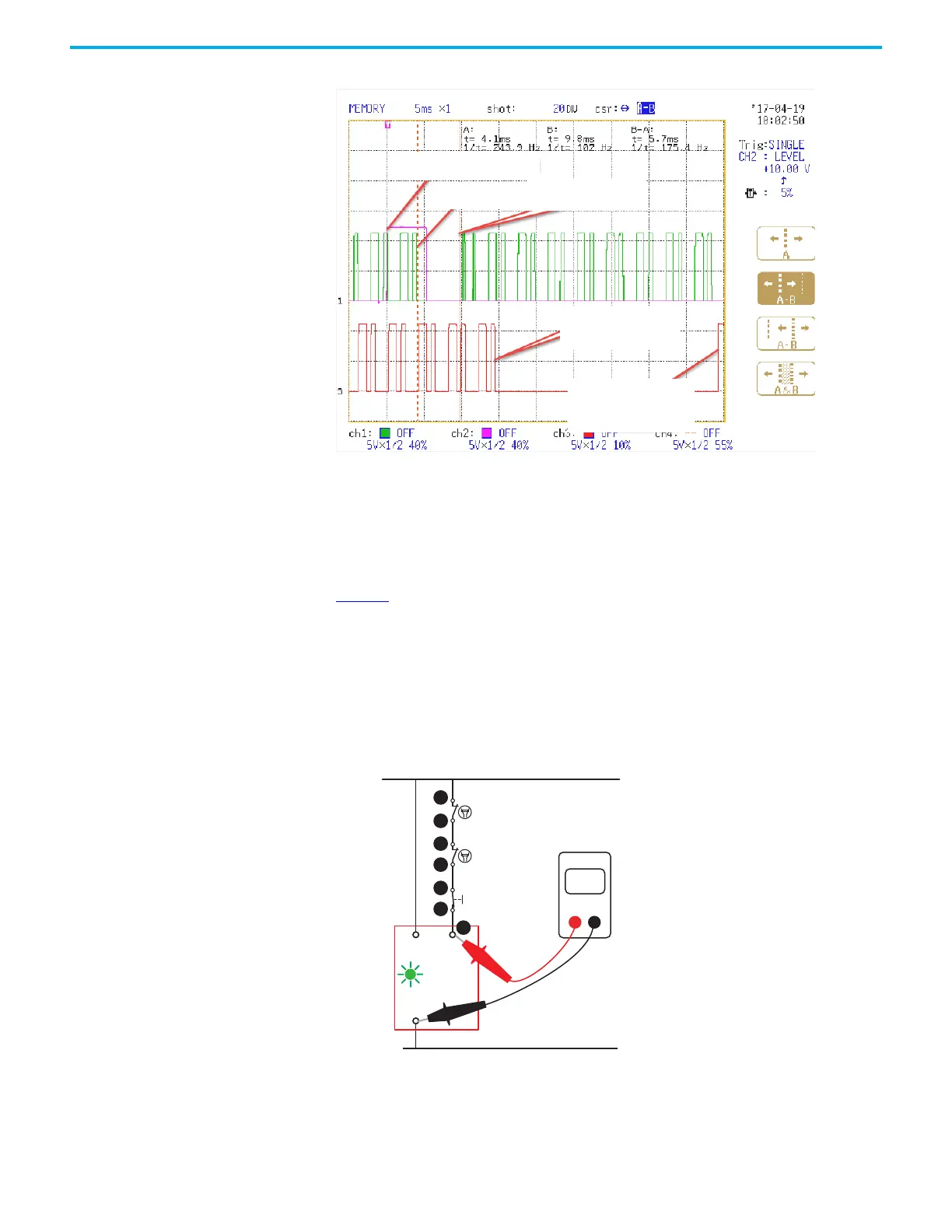
Figure 76 - Momentary Interruption of SWS Input
Check the Reset/Monitoring
Circuit (Step 5)
The OUT status indicator flashes green when the inputs to the GSR safety relay are satisfied
and the GSR safety relay is ready to turn on its outputs. The OUT status indicator flashes green
at a 1 Hz rate. The GSR safety relay is waiting for the appropriate reset signal at terminal S34.
If the OUT status indicator is flashing green, but the safety relay does not turn on its outputs
when the Reset button is pressed, measure the voltage at terminal S34 (point 1) as shown in
Figure 77
. If 24V is not present when the Reset button is pushed, then check the other
connections (points 2...7) in the circuit. If 24V is present at terminal S34, then you must
consider the reset configuration.
• Automatic/manual: The GSR safety relay must be replaced as the output status
indicator must turn steady green as soon as the voltage was present at terminal S34.
• Monitored/manual: If the output status indicator does not turn steady green when
voltage at S34 is present between 0.25…3 seconds, then the GSR safety relay must be
replaced.
Figure 77 - Measure Reset/Monitoring Circuit Voltage
Command to open SWS
SWS opens
SW closes in 5.7 ms
The Downstream unit
turns off its Output
The Downstream unit
turns its Output back on
auto-reset
+24V DC
24V DC Com
S34
OUT
A1
A2
1
2
3
4
5
6
7
24
Volts
DMM
(

 Loading...


