Rockwell Automation Publication 440R-UM013G-EN-P - December 2022 65
Chapter 11 Troubleshooting
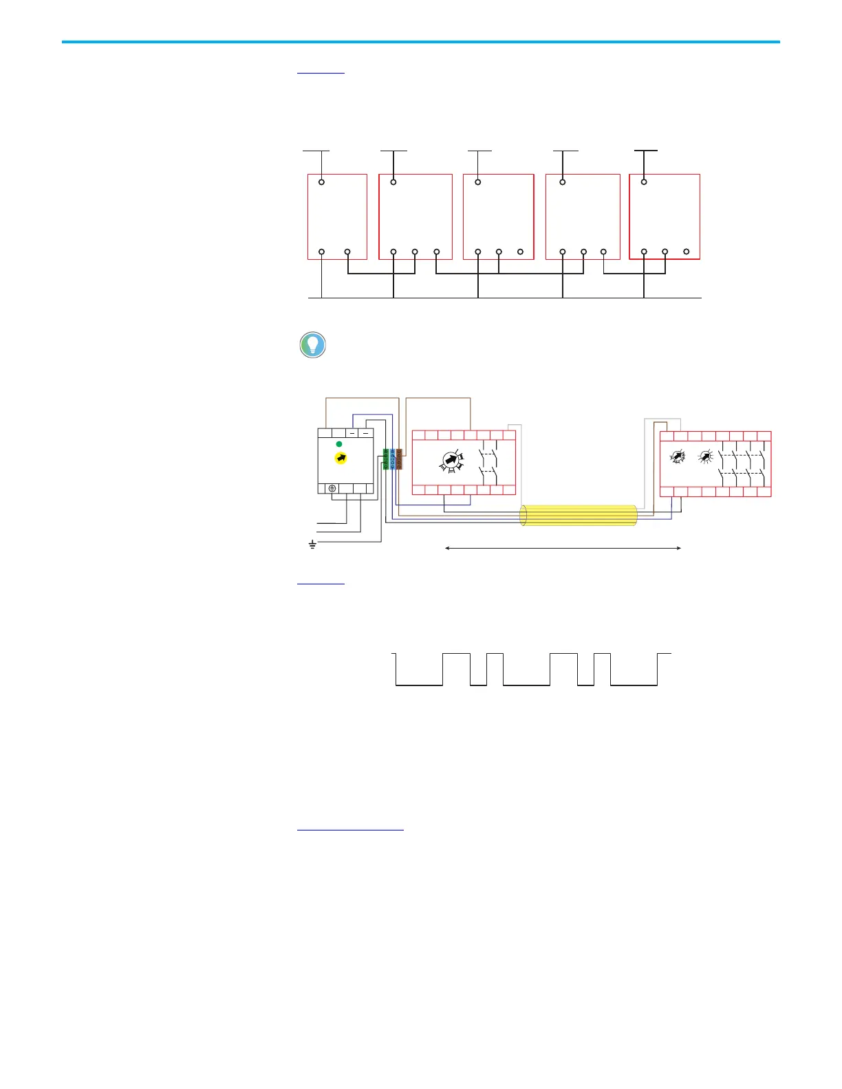
Figure 73 shows an example of an SWS connection. Note the L11 terminal (which is the SWS
output) can be connected to multiple L12 terminals (SWS input), but the L12 terminal cannot be
connected to multiple L11 terminals.
Figure 73 - Example SWS Connections
Figure 74 - SWS with Shielded Cable
Figure 75 shows the characteristics of SWS signal when it is active. It starts with a 1 ms pulse,
followed 700 µs later by a 500 µs pulse. This waveform is repeated every 4 ms. When inactive,
the SWS is 0V.
Figure 75 - SWS Waveform
When the signal is active, use a digital multimeter to measure the voltage. The digital
multimeter shows 8…9V.
If a fault occurs with either an SWS input or SWS output, then that circuit is held high. If a
digital multimeter reads a voltage measurement of approximately 21V, the signal is high. The
PWR/Fault status indicator flashes red five times.
Figure 76 on page 66
shows an example timing of a momentary interruption of the SWS input.
If a momentary interruption of the SWS signals occurs, the downstream unit ignores
interruptions less than 5.7 ms. The downstream unit automatically turns off and then back on
when the interruption is greater than 5.7 ms.
The momentary interruption does not cause a 'recovery' type fault, where the output turns off
and stays off and requires a further cycling of the SWS signal.
For long wire runs of the SWS signal, a shielded cable can be necessary to help
prevent nuisance faults from electromagnetic and motor noise.
L12 L11
A1
A2
+24V DC +24V DC
L11
A1
A2 L12 L11
A1
A2 L12 L11
A1
A2
+24V DC
SWS SWSSWS
+24V DC
L12 L11
A1
A2
+24V DC
24V DC Com (must have common reference)
CI or SI DI EM DIS EMD
A1
L12
X32 B1 B2
L11 38
17 27 37 47
4818 28A2
EMD
440R-EM4R2D
1
2
3
4
5
67
8
9
10
TIME
0
1
2
3
4
56
7
8
9
RANGE
+24V DC
24V Com (0V)
L
L
++
N
N
1606-XLP95E
24-
28V
DC ok
120…240V AC
PE
Protective Earth Ground
Connect Shield to PE
SWS signal
Shielded cable
Connect unused conductors to 0V
SWS wiring distances between 10…30 m
A1
S11 S21
S12 S22 S32
L11 Y32L12
13
14
S42 23
24
S34
A2
DI
440R-D22R2
0
1
2
3
4
56
7
8
LOGIC

 Loading...


