8 Rockwell Automation Publication 440R-UM013G-EN-P - December 2022
Preface
Definitions Publication AG-7.1 contains a glossary of terms and abbreviations that Rockwell Automation
uses to describe industrial automation systems. The following is a list of specific terms and
abbreviations that are used in this manual.
Additional Resources These documents contain additional information concerning related products from Rockwell
Automation.
You can view or download publications at rok.auto/literature
.
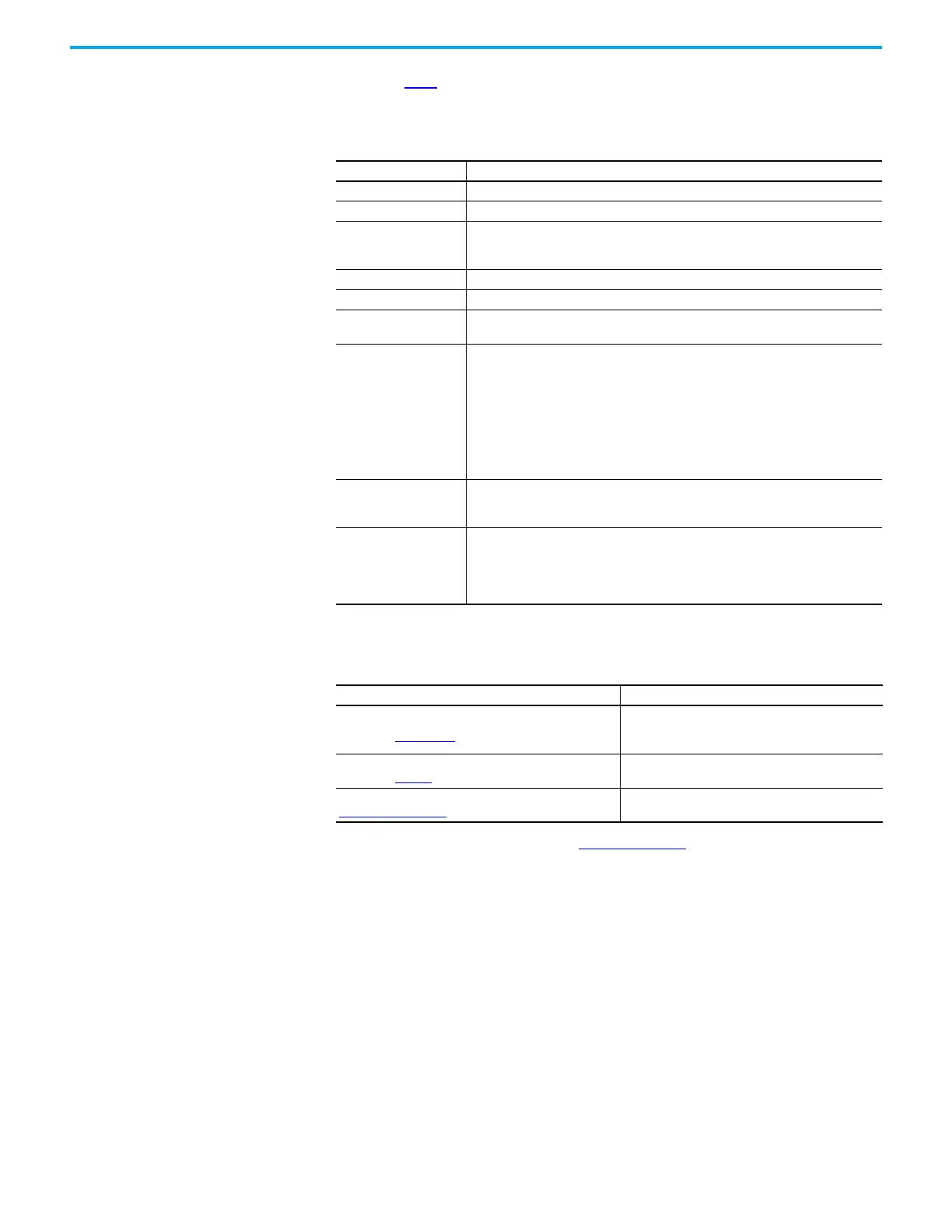
Table 1 - Definitions
Term Definition
N.C. Normally Closed - An electrical contact whose normal state is in the closed position.
N.O. Normally Open - An electrical contact whose normal state is in the open position.
OSSD
Output Signal Switching Device - Typically a pair of solid-state signals that are pulled
up to the DC source supply. The signals are tested for short circuits to the DC power
supply, short circuits to the DC common and shorts circuits between the two signals.
PLC A programmable logic controller or a programmable automation controller.
Reaction time The time between the true states of one input to the on state of the output.
Recovery time
The time that is required for the input to be in the LO state before returning to the HI
state.
Reset
Safety relays offer two types of reset - Monitored manual and automatic/manual.
• Monitored Manual - The safety relay performs a reset function when the reset signal
goes from off to on and then back to off in a prescribed time-period. The reset
occurs on the trailing edge.
• Automatic/Manual - The safety relay performs a reset function if the reset input is
on. If the reset input is connected directly to 24V, the reset function is executed
immediately when the inputs become closed or active. If a contact (push button or
equivalent device) is used in the reset input, the reset function is executed on the
leading edge of the reset signal (if the inputs are closed or active).
Response time
Describes the time between the trigger of one input to the off state of the output.
Throughout this manual, the safety outputs are described as turning off immediately,
which means that the safety outputs turn off within the response time.
SWS
Single Wire Safety - A unique, safety-rated signal that is sent over one wire to indicate
a safety status. The SWS can be used in safety systems that require Category 4,
Performance Level e, per ISO 13849-1 and safety integrity level (SIL) 3, per IEC 62061
and IEC 61508. When an SWS signal is present, this publication describes this state as
ACTIVE or on. This signal is also referred to as the logic link signal.
Resource Description
Guardmaster EtherNet/IP Network Interface User Manual,
publication 440R-UM009
Describes the procedures that you use to install, wire,
configure, troubleshoot, and use EtherNet/IP™
modules.
Industrial Automation Wiring and Grounding Guidelines,
publication 1770-4.1
Provides general guidelines for installing a Rockwell
Automation® industrial system.
Product Certifications website,
rok.auto/certifications
.
Provides declarations of conformity, certificates, and
other certification details.

 Loading...


