Rockwell Automation Publication 440R-UM013G-EN-P - December 2022 69
Chapter 11 Troubleshooting
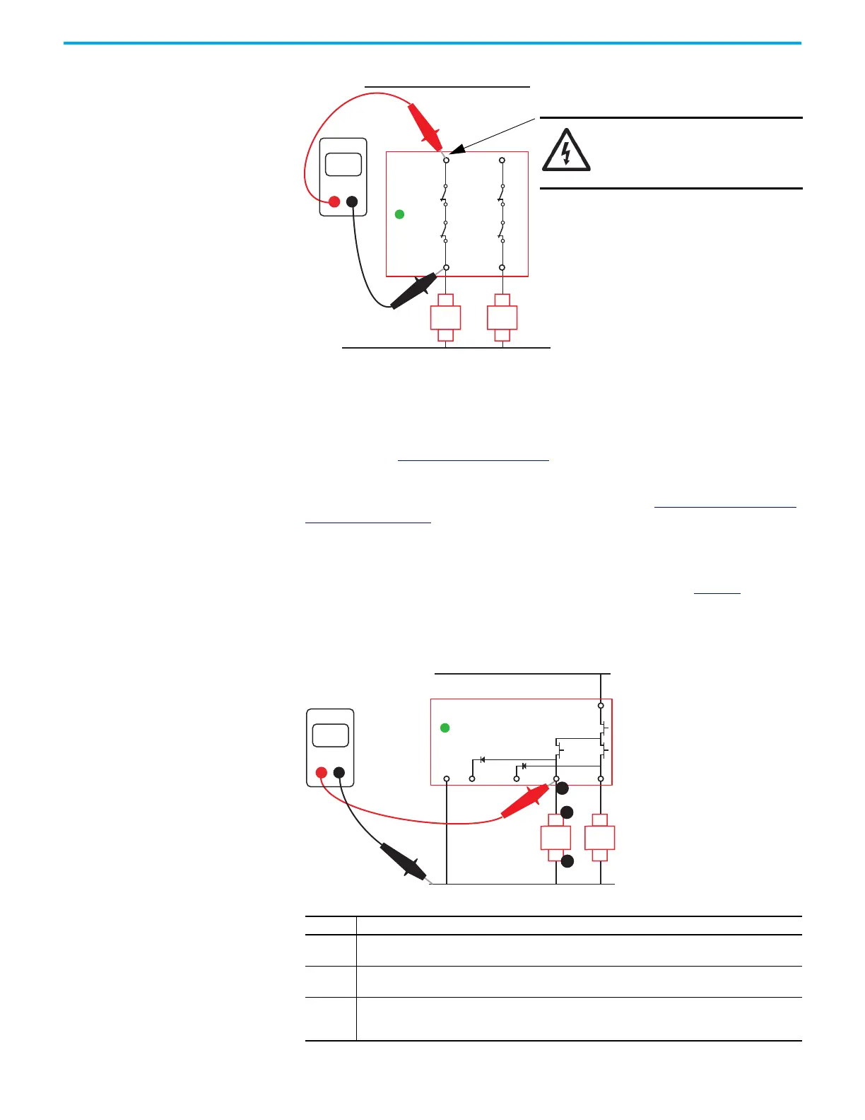
Figure 80 - Measure the Contact Resistance
OSSD Output Issues
If the OUT status indicator is steady green, but the output device that is connected to terminal
14 or 24 does not energize, begin troubleshooting by checking the voltage at the output
connections. See Check the OSSD Connections
.
If the OUT status indicator is steady green, but the PowerFlex® drive indicates that the safety
circuit is open, check the connections to the PowerFlex drive. See Check the PowerFlex Drive
Connections on page 70.
Check the OSSD Connections
Confirm that voltage is present at the safety relay terminals and the load. Figure 81 shows an
example of the measurement points for one output channel (terminal 14). Since most safety
circuits consist of two channels, repeat the checking on the second channel (terminal 24).
Figure 81 - OSSD Output Connections
Step Description
1
The voltage at 14 must be slightly less than the supply voltage. If not, then the DIS safety relay must be
replaced.
2
The voltage at A1 must be slightly less than the supply voltage and must be the same voltage as
measured at terminal 14. If not, check for an open circuit (broken wire) between terminal 14 and A1.
3
The voltage at A2 must be zero. If not, check for an open circuit between A1 and the voltage supply
ground connection. If A2 measures zero volts and A1 measures the supply voltage, then K1 is not
operating properly, and must be replaced.
14
24
< 1
13
OUT
23
Ohms
DMM
K1
A2
A1
K2
A2
A1
SHOCK HAZARD: Remove the
power connections to terminal
13 before measuring the
contact resistance.
+V supply
0V
34 44 14 24
A1
A2
23
Volts
DMM
1
OUT
K1
A2
A1
K2
A2
A1
2
3

 Loading...


