Rockwell Automation Publication 440R-UM013G-EN-P - December 2022 73
Chapter 11 Troubleshooting
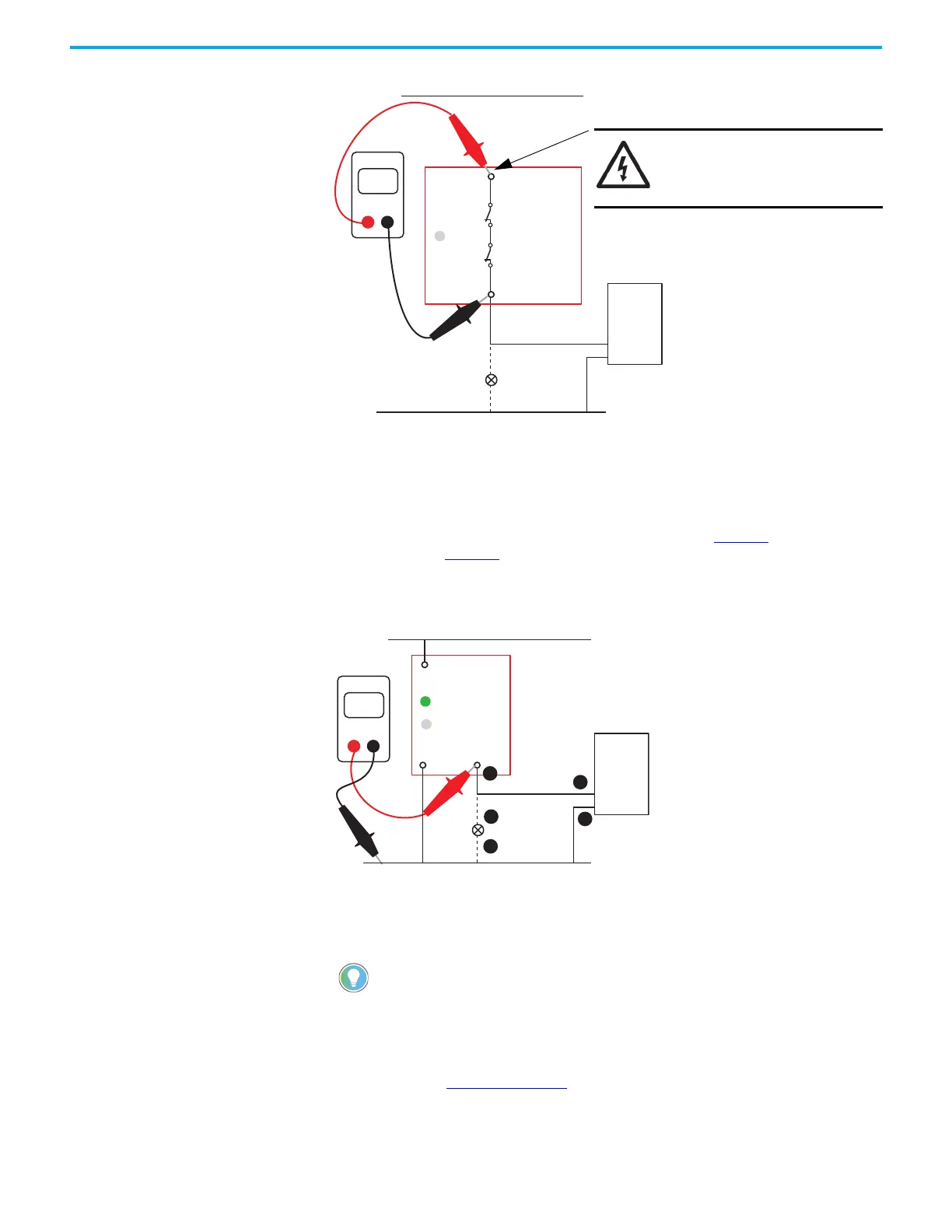
Figure 87 - Measure Contact Resistance of Aux Output Terminals
Check the Y32 Output
When the OUT status indicator is off, terminal Y32 does not turn on, or when the safety outputs
are off, the Y32 output must be on. This condition is true for both faulted and running states.
Use a digital multimeter to measure the voltage at Y32 (point 1 in Figure 88
). The voltage must
be around 23V DC. Figure 88 shows a typical schematic for the aux output; the aux signal can
go to a PLC input or to a status indicator on a control panel. If it is 23V, then check the
remaining points (2…5). If Y32 measures 0V, then the safety relay must be replaced.
Figure 88 - Measure Y32 Voltage
Check the X32 Output
When the OUT status indicator is off, terminal X32 does not turn on.
Correct the fault and cycle power. The safety relay must be reconfigured to correct the fault.
If the PWR/Fault status indicator is green, then measure the voltage at terminal X32 with a
digital multimeter. Figure 89 on page 74
shows a typical usage of X32 (point 1) as the source
for the monitoring circuit. The voltage must be around 23V DC. If it is 23V, then follow the
circuit and check the voltage at each of the remaining points (2…6). If X32 measures 0V, then
the safety relay must be replaced.
This operation is proper for the EM and EMD safety relays if they are in a
nonrecoverable faulted state. If so, then the PWR/Fault status indicator is steady
red or flashing red.
SHOCK HAZARD: Remove the
power connections to terminal
41 before measuring the
contact resistance.
+V supply
0V
PLC
Input
A2 Y32
A1
23
Volts
DMM
0V
1
2
3
4
5
Com
OUT
+24V DC
PWR/Fault
PLC
Input
CI, DI, DIS, or SI

 Loading...


