22 Rockwell Automation Publication 440R-UM013G-EN-P - December 2022
Chapter 3 Power, Ground, and Wire
When changing the function from mechanical switches or OSSDs to safety mats, GSR safety
relays must go through the complete configuration process.
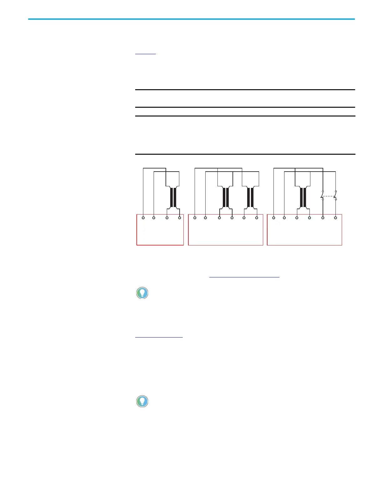
Figure 12
shows the typical connections for safety mats. You notice the reverse of the wiring
between a device with 2 N.C. contacts and the safety mat.
When a safety mat is used, safety relays cannot detect short circuits between the inputs or
between the inputs and 24V DC. Test these conditions during validation.
Figure 12 - Example One Connection to Safety Mats
Because the safety mats are parallel plates, they have a significant capacitive effect. The
larger the safety mat, the more capacitance. If the capacitance is too large, the safety relay
does not function properly. See Capacitance Effect
on page 61 for further information.
Figure 13 on page 23
shows an example where the safety mat and a device with pulse-testing
OSSD outputs are connected to the DI or DIS safety relay. In this example, performance is
independent of the input connection (IN1 or IN2). The devices must be connected and circuits
closed during the configuration process and upon normal power-up. Upon normal power-up,
the DI and DIS safety relay attempts to determine whether a safety mat is connected. During
the power-up test, the DI and DIS safety relay may detect the pulse test of the OSSD device at
the same time it is trying to determine if a safety mat is connected and determine that a
configuration is incorrect. If this situation occurs, another power-up cycle is required.
IMPORTANT For fault detection purposes, configure GSR safety relays for monitored
manual reset when connected to safety mats.
IMPORTANT When using safety mats, set the DI and DIS safety relays for AND logic. If
you use only one safety mat, connect the second input with jumpers or to
another safety device. If another safety device connects to the second
input, the outputs of the safety device must be on during configuration
and during power-up.
Allen-Bradley® Guardmaster MSR safety relays can be tickled by tapping on the
safety mat, which generated fast cycles. This activity caused the safety relay to
fault because the fast cycles violated the recovery time specification. GSR safety
relays have a faster recovery time (30 ms). However, there is a small window of
actuation times (around 20 ms) that can cause a GSR relay to enter a faulted state
(steady red PWR/Fault indicator); a power cycle is required to clear the fault.
When you combine mats with devices with OSSD outputs, the duration and period
of the OSSD pulses affects the potential of a power-up fault. OSSD outputs with
shorter pulse widths and longer periods contribute to fewer power-up faults.
S11 S21 S22 S12 S42 S32S11 S21 S22 S12 S11 S21 S22 S12 S42 S32
Mat 1
Input 1
Input 1 Input 2
Pulse
Testing
Outputs
Pulse
Testing
Outputs
CI and SI
DI and DIS
Input 1 Input 2
Pulse
Testing
Outputs
DI and DIS
Mat 1
Mat 2 Mat 1 EM Device

 Loading...


