106 Rockwell Automation Publication ICSTT-RM447M-EN-P - July 2019
Chapter 6 Specifying a New Controller
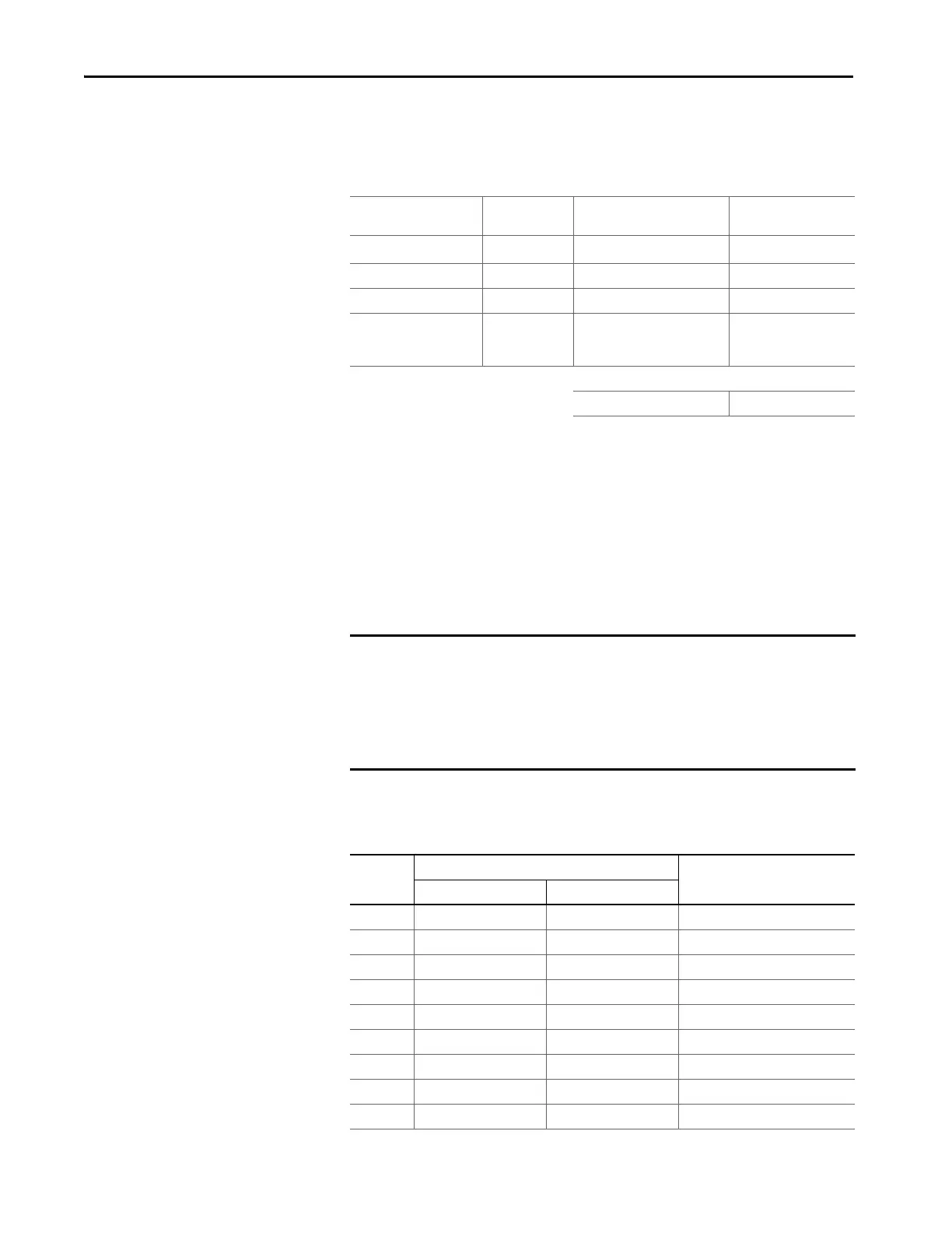
Table 20 - Field Loop Power Heat Dissipation
The field loop power heat dissipation is generated from the input voltages and
currents + the output currents:
1
The maximum field loop power heat dissipation for analogue outputs should
be calculated at an output current corresponding to the smaller of the
Maximum Channel Output Current OR Field Voltage/(2 x Load Resistance)
Backplane Electrical Ratings
To comply with UL/CSA standards use the following voltage and current
ratings for the Processor and I/O Backplanes when designing your power
distribution:
Table 21 - Maximum Electrical Rating Values
Item Number of Field
Loops
Field Loop Power Heat
Dissipation
Subtotal
(W x 3.412 BTU/hr)
Digital Inputs × Input Voltage (V)/5125 =
Analogue Inputs × Input current (A) x 135 =
Digital Outputs x Output current (A) x 0.57 =
Analogue outputs x (Field voltage(V) x Output
Current (A) - load Resistance (Ω)
x Output current (A)
1
=
Tot al :
IMPORTANT These are the maximum allowed electrical ratings given by UL
for the backplane load installed with the relevant TAs and
modules. They are not operating values so don't use them to
calculate the controller power consumption or heat
dissipation values. Refer to the separate topics on estimating
Heat Dissipation and Power Consumption.
Module Back-plane Electrical Ratings Input/Output Electrical Ratings
Voltage Range (Vdc) Maximum Current (mA)
9100 18-32 10.4A (400 mA per slot) -
9300 18-32 9.6A (400 mA per slot) -
9110 18-32 380 -
9401 18-32 260 Input: 18-32 Vdc @ 24 mA
9402 18-32 260 Input: 0-32 Vdc @ 6.5 mA
9431 18-32 260 Input: 0-32 Vdc @ 6.5 mA
9432 18-32 260 Input: 18-32 Vdc @ 24 mA
9481 18-32 260 Output: 18-32 Vdc/0-20 mA
9482 18-32 260 Output: 18-32 Vdc/0-20 mA

 Loading...


