Rockwell Automation Publication ICSTT-RM447M-EN-P - July 2019 73
AADvance System Architectures Chapter 4
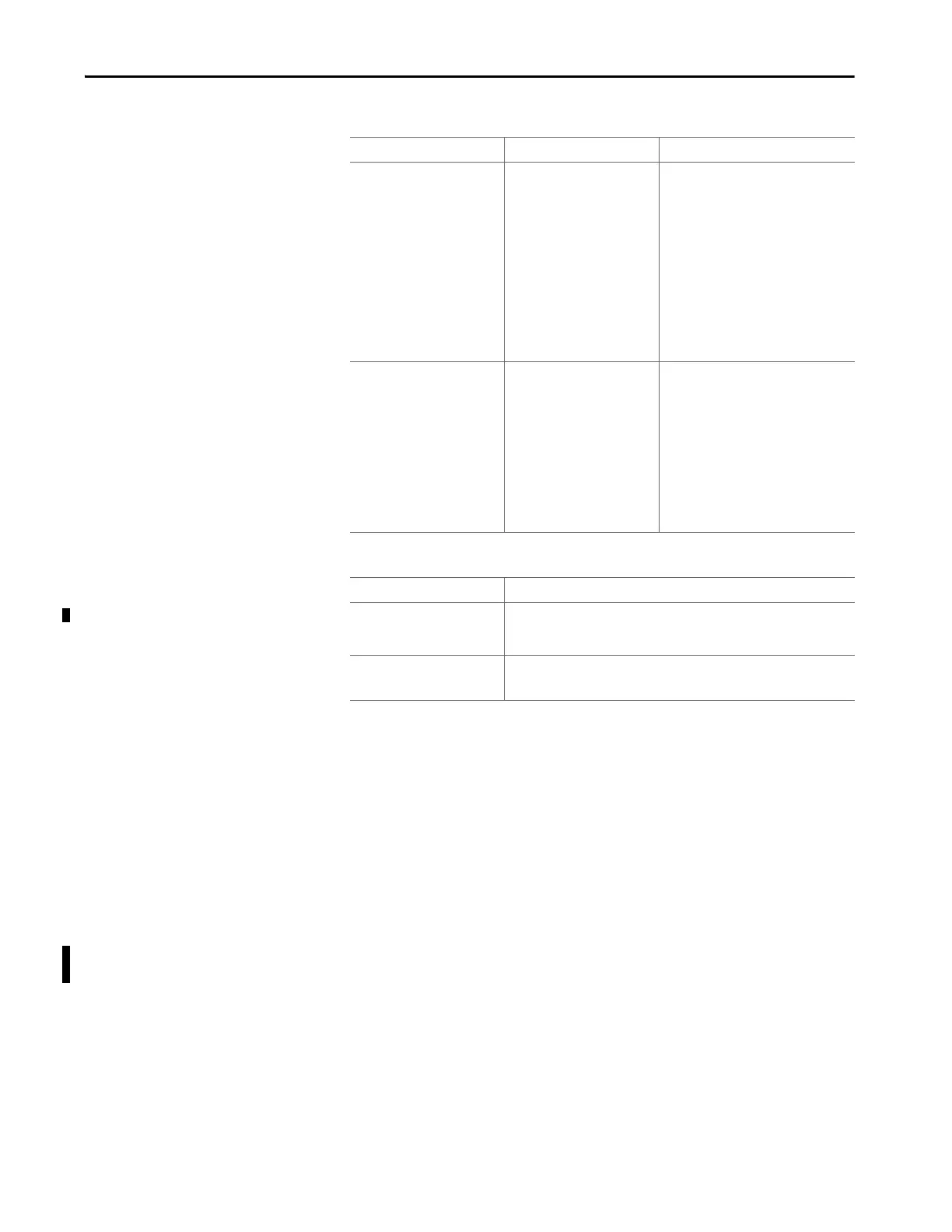
Table 14 - Output Modules
Table 15 - Auxiliary Modules
Example Architectures with
Approved Modules
The controller supports a range of architectures as defined in the previous
chapter. This chapter describes how to assemble a range of architectures
configurations and includes selected examples that illustrate the alternative
options. The modular construction of the controller makes it easy to create
module arrangements and these can be tailored for a specific application.
Standard Architectures
The standard AADvance modules can be arranged to supply two fundamental
architectures based on dual and triple modular redundant processors modules.
To these can be added I/O modules for redundant and/or fault tolerant
configurations based on the following arrangements:
• Input modules in simplex, dual and triple modular redundant
formations
Modules Certified Configuration Conditions
Digital Outputs
T8451, 24 Vdc, 8 channel
+
T9851/2 TA,24 Vdc, 8 Channel,
Simplex/Dual
1oo1, 1oo2 or 1oo2D De-energize to action (normally
energized): SIL 3 with 1 or 2 modules
fitted. (1oo2D with dual output modules
fitted).
Energize to action (normally de-
energized): SIL 2 with 1 module fitted and
SIL 3 with 2 modules fitted.
A faulty digital output module must be
repaired or replaced within the MTTR
which was used in the PFD calculation. This
rule applies to all simplex digital output
modules and to dual digital output
modules in energize to action applications.
Analogue Outputs
T9481/T9842 Analogue Output
Module, 3/8 Ch, Isolated
+
T9881/T9882, TA, 8Ch, Simplex/
Dual
1oo1, 1oo2 or 1oo2D SIL 3 with 1 or 2 modules fitted where the
safe state is less than or equal to 4 mA
SIL 3 with 2 modules fitted where the safe
state is more than 4 mA (1oo2D with dual
output modules fitted).
A faulty analogue output module must be
repaired or replaced within the MTTR
which was used in the PFD calculation. This
rule applies to all simplex analogue output
modules and to dual analog output
modules where the safe state is > 4 mA
Modules Conditions
Processor Base
T9100
Safety-related and can be used for safety critical applications in SIL 2
applications with 2 modules fitted or SIL 3 applications with 2 or 3 modules
fitted
I/O Base
T9300 (3-way)
Safety-related and can be used for safety critical applications in SIL 3.

 Loading...


