Rockwell Automation Publication ICSTT-RM447M-EN-P - July 2019 109
Specifying a New Controller Chapter 6
• Make sure that the power distribution cabling is sized to allow the
maximum prospective fault currents and tolerable voltage losses. This is
specifically important where floating supplies are employed and other
power sources can cause high prospective fault currents if multiple earth
faults occur.
Estimating Power
Consumption
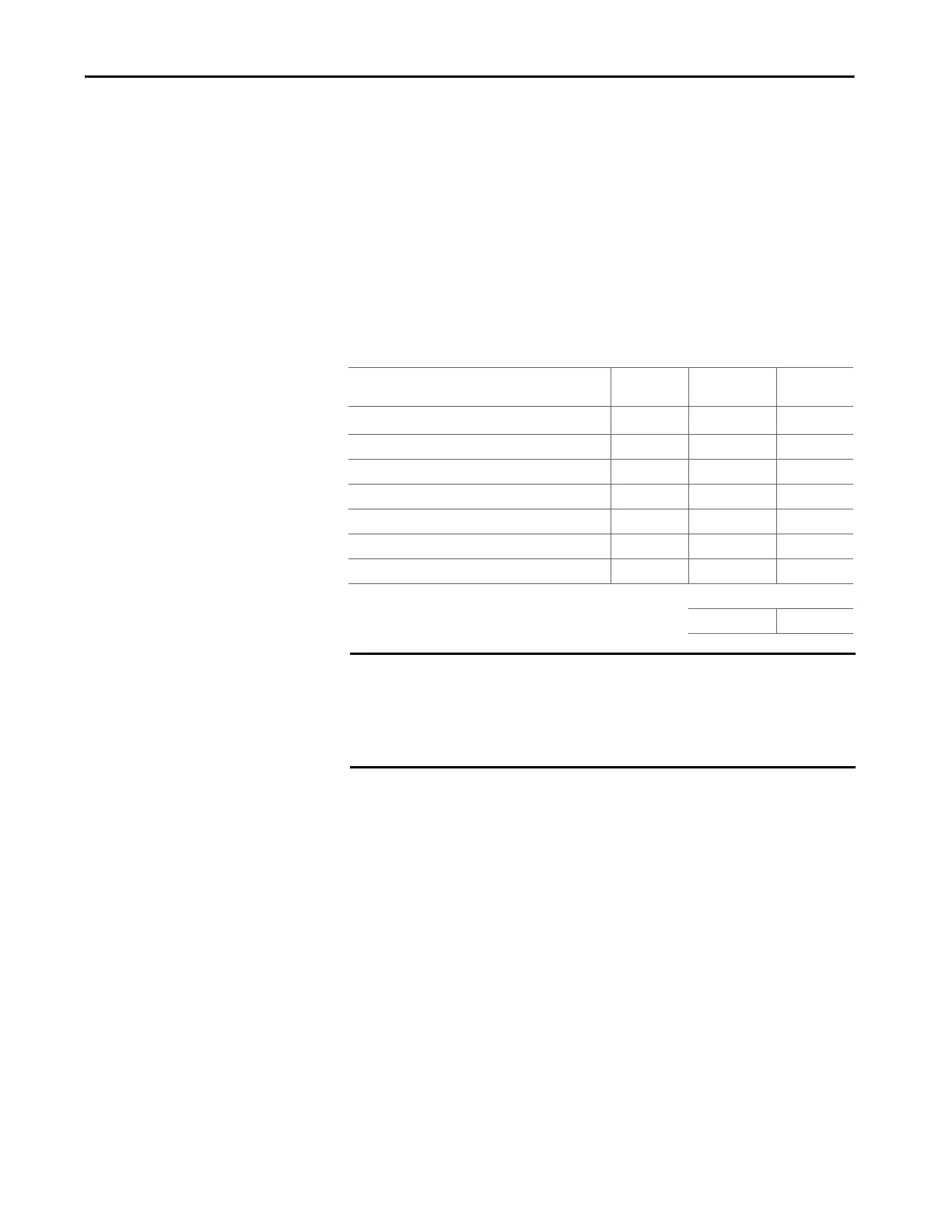
To estimate the power supply requirements (power supply sizing) you need to
know the power consumption of all the modules. Use the following table to
estimate the system power consumption.
Table 22 - Module Supply Power Consumption
Field Power Consumption
To estimate overall controller power dissipation it is necessary to include the
field power component dissipated within the controller. Refer to the table
"Field Loop Power Heat Dissipation". The field power requirements should be
calculated separately and is dependent on the number and type of field
elements. Refer to the specifications for the Digital and Analogue output
modules for details of the channel output electrical specifications.
Item Number of
Modules
Power
Consumption
Subtotal (W)
T9110 Processor Module × 8.0 W =
T9401 Digital Input Module 24 Vdc, 8 channel × 3.3 W =
T9402 Digital Input Module 24 Vdc, 16 channel × 4.0 W =
T9431 Analogue Input Module, 8 channel × 3.3 W =
T9432 Analogue Input Module, 16 channel × 4.0 W =
T9451 Digital Output Module, 24 Vdc, 8 channel × 3.0 W =
T9482 Analogue Output Module, 8 channel, isolated × 3.6 W =
Tot al :
IMPORTANT The above figures are worst case values calculated from the range of
operating voltages and currents. If your system is required to meet UL/CSA
standards the power consumption and the corresponding electrical ratings
must not exceed the maximum electrical ratings given in the table included
in the topic "Backplane Electrical Ratings".

 Loading...


