Rockwell Automation Publication ICSTT-RM447M-EN-P - July 2019 143
System Build Chapter 9
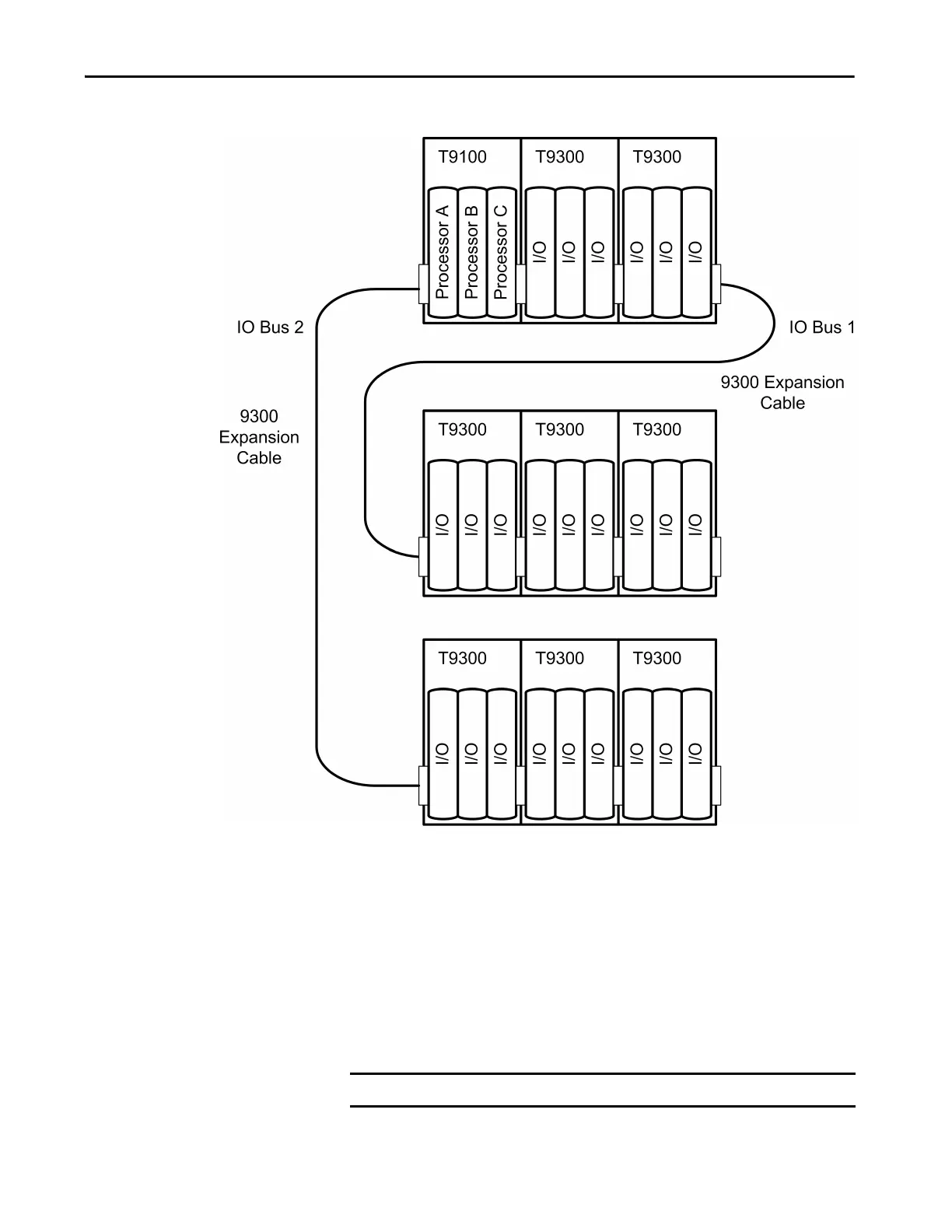
Figure 36 - Connecting Base Units with Expansion Cables
The expansion bus accessed from the right hand edge of the 9100 processor
base unit is designated I/O Bus 1, while the bus accessed from the left hand
edge is designated I/O Bus 2. The module positions (slots) in the I/O base
units are numbered from 01 to 24, the left most position being slot 01. Any
individual module position within the controller can thus be uniquely
identified by the combination of its bus and slot numbers, for example 1-01.
The electrical characteristics of the I/O bus interface limit the maximum
possible length of either of the two I/O buses (the combination of I/O base
units and expansion cables) to 8 meters (26.24 ft.).
NOTE The 9310 Expansion Cable is 2 m (6.56 ft.).

 Loading...


