144 Rockwell Automation Publication 20D-PM001D-EN-P - March 2019
Chapter 3 Troubleshooting
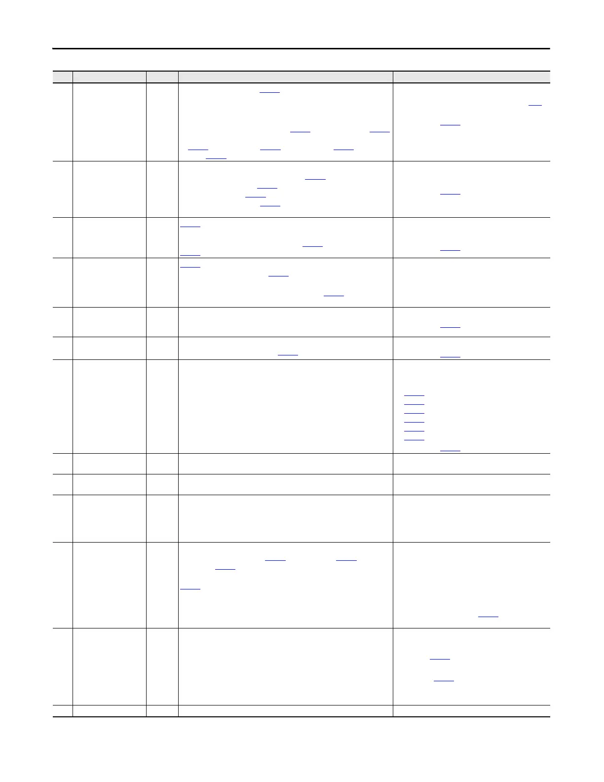
12 Motor OLoad Pend 2 A motor overload is pending. Par
308 [Output Current] is squared, scaled and
integrated over time. When this integrated value exceeds 0.5, this exception
event occurs.
The integrator's output can be viewed in Par 330 [Fault TP Data] when Par 329
[Fault TP l] is set to 13 “Mtr OL Outpt”. The overload integration rate is affected
by Par
336 [Motor OL Factor], Par 337 [Mtr I2T Curr Min], Par 338 [Mtr I2T Spd
Min] and Par 339 [Mtr I2T Calibrat].
• Reduce the mechanical load.
• Enter correct motor nameplate full load amps Par
2
[Motor NP FLA].
Configured with Par
371 [Mtr OL Trip Cnfg].
13 Motor Stalled 2 The motor has stalled. The three conditions listed below have occurred at the
same time for the amount of time specified in Par
373 [Motor Stall Time]:
1. The drive is not stopped (Par 150 [Logic State Mach] is not equal to zero).
2. The drive is on limit (Par 304 [Limit Status] is not equal to zero).
3. The drive is at zero speed (Par 155 [Logic Status], bit 13 “At Zero Spd” is
set).
• Increase the torque limit.
• Reduce the mechanical load.
Configured with Par
374 [Motor Stall Cnfg].
14 Inv OTemp Pend 2 Par
313 [Heatsink Temp] is within 10°C of maximum.
View the maximum heat sink temperature in Par 348 [Drive OL TP Data] when
Par 347 [Drive OL TP l] is set to 30 “fMaxHsDegc”.
• Reduce the mechanical load.
• Lower the ambient temperature.
Configured with Par
375 [Inv OT Pend Cnfg].
15 Inv OTemp Trip 1 Par
313 [Heatsink Temp] is above the maximum limit or a temperature sensor
has failed (shorted or open). See Par 346 [Drive OL Status], bit 0 “NTC Shorted”
and bit 1 “NTC Open”.
Or, the calculated junction temperature (displayed in Par 345 [Drive OL
JnctTmp]) of the power semiconductors in the inverter has been exceeded.
• Reduce the mechanical load.
• Lower the ambient temperature.
16 Inv OLoad Pend 2 The drive's operating point is approaching the intermittent current rating
limitation. If output current remains at or above present levels, an inverter
overload condition will occur.
Reduce the load on the drive.
Configured with Par
376 [Inv OL Pend Cnfg].
17 Inv OLoad Trip 2 The drive's operating point has exceeded the intermittent current rating and a
foldback to the continuous rating in Par
400 [Rated Amps] has occurred.
Reduce the mechanical load.
Configured with Par
377 [Inv OL Trip Cnfg].
18 Ext Fault Input 2 A digital input has detected an external fault. Enter a value of 3 “Ext Fault” or 38 “ExtFault Inv” in one
of the following parameters to configure an input to
detect an external fault:
• Par
825 [Digin 1 Sel]
• Par 826 [Digin 2 Sel]
• Par 827 [Digin 3 Sel]
• Par 828 [Dig In4 Sel]
• Par 829 [Dig In5 Sel]
• Par 830 [Dig In6 Sel]
Configured with Par 379 [Ext Flt/Alm Cnfg].
19 DSP Memory Error 1 Flash memory does not match the SRAM memory. Cycle the drive power. If the fault remains, replace the
Main Control board.
20 DSP Device Error 1 A DSP (Velocity Position Loop) interrupt task has not been completed in the
allotted time.
Cycle the drive power. If the fault remains, replace the
Main Control board.
22 Over Frequency 1 The Encoderless algorithm failed to converge on the correct speed. Two
possible causes include:
1. The Velocity regulator is attempting to run below the motor’s slip speed.
2. The Frequency regulator “pulls out” and the commanded motor frequency
slows to the maximum frequency limit.
23 MC Commissn Fail 1 The drive has failed to complete either the Motor Autotuning procedure or the
Power Circuits Diagnostics test. Par
463 [MC Diag Error 1], Par 464 [MC Diag
Error 2], and Par 465 [MC Diag Error 3] display Motor Autotuning and Power
Circuit Diagnostic faults.
Par
465 [MC Diag Error 3] - Drive current, inductance, voltage and speed are
not within motor nameplate specifications. This fault occurs most frequently
on low horsepower motors.
• Verify that the motor nameplate data is entered
correctly into the drive.
• Verify that the motor is wired for the correction
voltage entering into the drive.
• Verify that the encoder (if used) and velocity
feedback is correct.
• Change the tuning mode in Par
515 [FVC Tune Config]
to 9 “NoRotate Tune”.
24 DC Bus Overvolt 1 A DC Bus overvoltage has occurred. • Verify the AC Line.
• Verify that either the brake or bus regulator is
enabled (Par 414 [Brake/Bus Cnfg], bit 0 “Brake
Enable” or bit 3 “Bus Reg Enable”, respectively).
• Verify that Par
128 [Regen Power Lim] is set properly.
• If Par 414 [Brake/Bus Cnfg] bit 0 “Brake Enable” is set,
verify that the braking resistor is properly sized.
25 Inv Trans Desat 1 The IGBT detects a transistor failure (Desaturation).
No. Name Type
(1)
Description Action
 Loading...


