Rockwell Automation Publication 2198-RM003B-EN-P - November 2020 67
Chapter 4 Dimensions, Cables, and Wiring
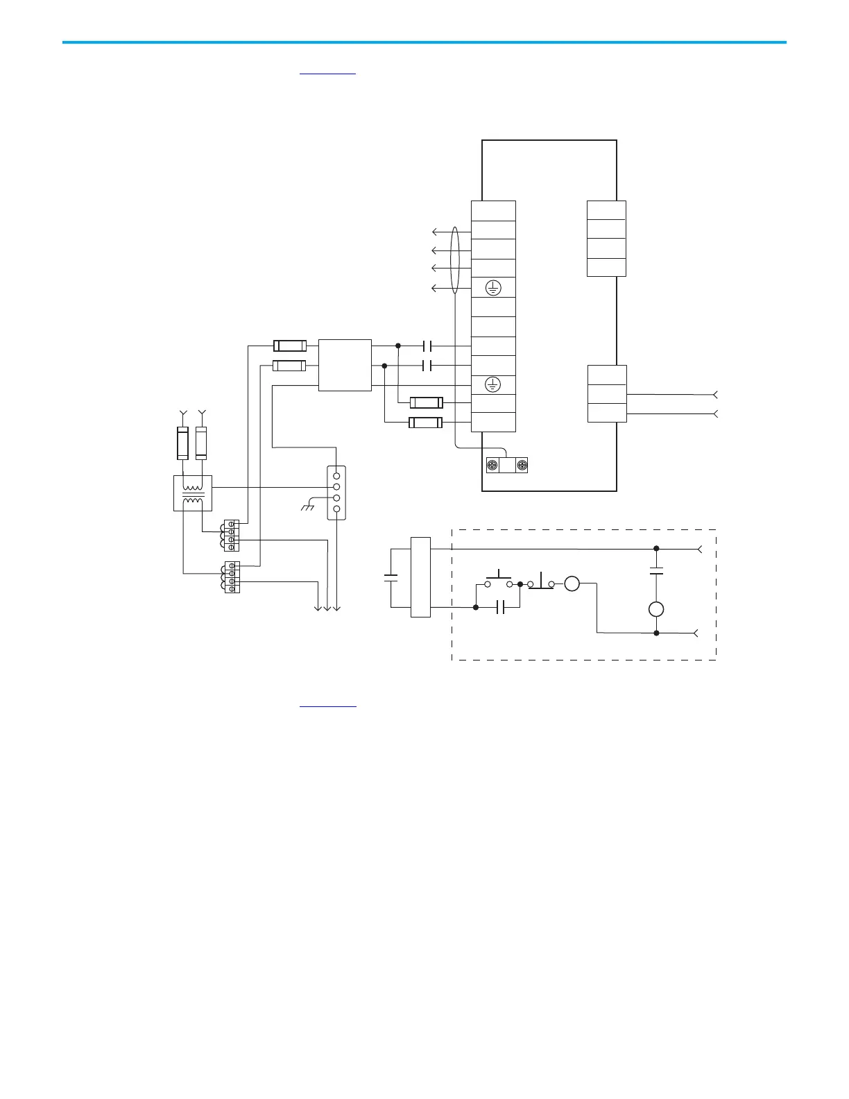
Figure 33 is the power wiring diagram with 24V DC control string for the
2098-DSD-030x-xx drive (non-Sercos).
Figure 33 - Typical Power Wiring on Ultra3000 (230V) System (2098-DSD-030x-xx)
Figure 34 is the power wiring diagram with 24V DC control string for
2098-DSD-075x-xx and 2098-DSD-150x-xx Ultra3000 drives (non-Sercos).
TB1
U
V
W
DC+
DC-
L1
L2/N
L1 AUX
L2/N AUX
L2/N
L1
CN1
43
44
TB2
1
2
3
43
44
CN1
43
44
2098-DSD-030x-xx
Ultra3000
Digital Servo Drive
AC Input Power
Connections
Motor Power
Connections
Single-phase
AC Line Filter
Input Fusing *
Single-phase Input
100...240V AC rms
Fused Disconnect
or Circuit Breaker *
Isolation
Transformer *
Chassis
Bonded Cabinet
Ground Bus *
Terminal
Blocks *
To additional
Ultra3000 drive.
Three-phase
Motor Power
Connections
Cable Shield
Clamp
* Indicates User-supplied Component
STOP *
START *
CR1 *
CR1 *
CR1 *
M1 *
N.O. Relay Output+
N.O. Relay Output-
24V DC
M1 *
External Passive
Single-phase AC Line
50/60 Hz
Input Fusing *

 Loading...


