Rockwell Automation Publication 2198-RM003B-EN-P - November 2020 69
Chapter 4 Dimensions, Cables, and Wiring
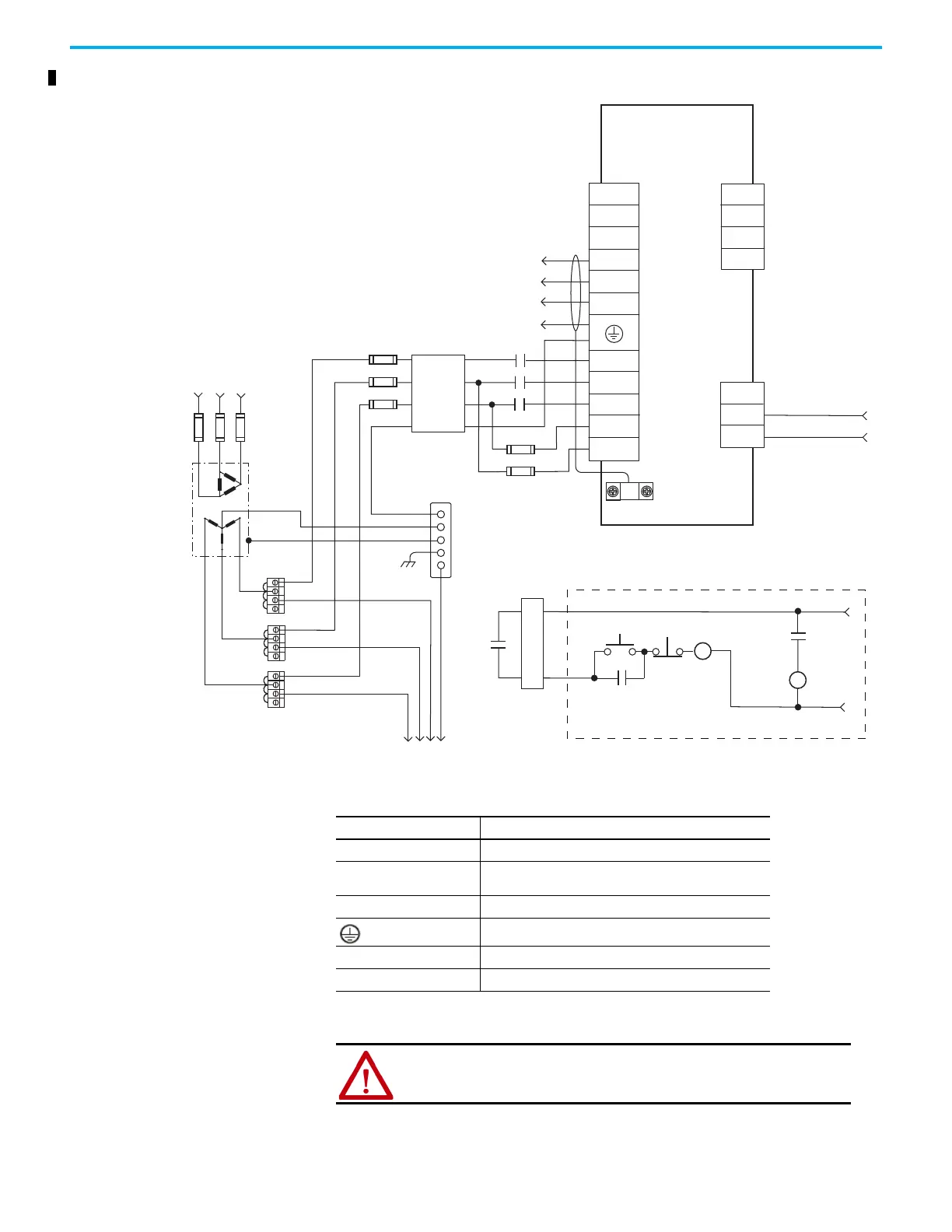
Figure 35 - Typical Power Wiring of Ultra3000 System (2098-DSD-HVxxx-xx and -HVxxxX-xx)
Pay attention to the followings when wiring:
• Separate L1, L2, L3, L1C, L2C, and U, V, W from other wires. The interval
should be at least 30 cm (11.8 in.).
TB1
DC+
DC-
W
V
U
L2
L3
CN1
43
44
L1
TB2
1
2
3
L3
L2
L1
L1 AUX
L2/N AUX
43
44
CN1
43
44
Ultra3000
Digital Servo Drives
2098-DSD-HVxxx-xx and
-HVxxxX-xx
External Passive
Shunt Connections
Motor Power
Connections
Three-Phase
Motor Power
Connections
Input Fusing*
M1*
Three-Phase AC Line
50/60 Hz
Fused Disconnect
or Circuit Breaker*
Isolation
Transformer*
Three-Phase Input
100-240V ac RMS
*INDICATES USER-SUPPLIED COMPONENT
To additional
Ultra3000 drives
Bonded Cabinet
Ground Bus*
Input Fusing*
Three-phase
AC Line
Filter
Note 6
Cable Shield
Clamp
AC Input Power
Connections
N.O. Relay Output+
N.O. Relay Output-
START*
START*
STOP*
M1*
CR1
CR1
CR1
24V DC
Table 60 - Connectors and Terminal Blocks Detail
Symbol Description
L1, L2, L3 Main power input connector
L1C, L2C, P1, P2, DC–
Control power input and DC bus connector (200V class
drive)
U, V, W Motor power output connector
Ground terminals
DC+, ISH, ESH Shunt Resistor Connector
I/O Input/Output signal connector-PLC and I/O functions
ATTENTION: When the power is off, do not touch L1, L2, L3 and U, V, W,
P1, P2, DC- and DC+, ISH, or ESH because there may be hazardous voltage
present. You must wait until the Charge light is off.

 Loading...


