152 Rockwell Automation Publication 7000-UM202H-EN-P - November 2023
Chapter 3 Control Component Definition and Maintenance
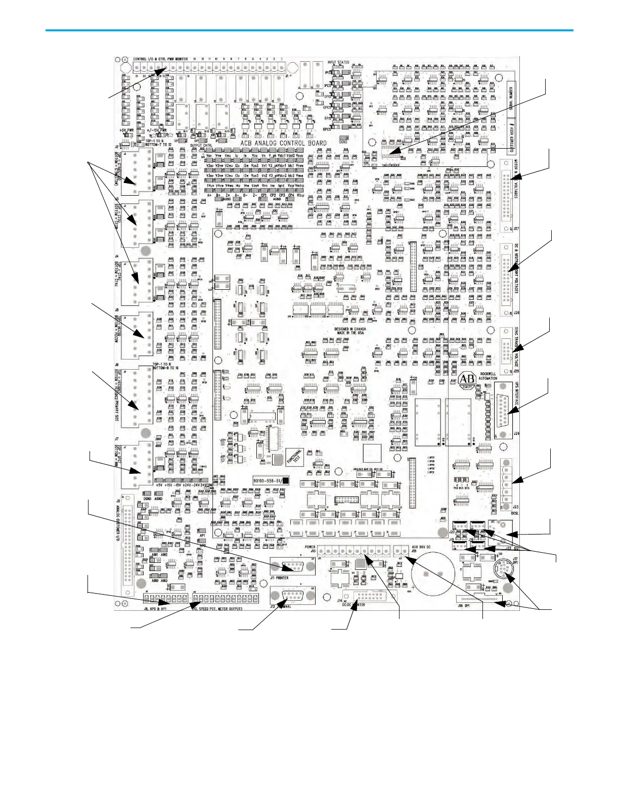
Figure 130 - ACB Analog Control Board
The analog control board receives all of the analog signals from the internal
components of the drive. This includes the current and voltage feedback
signals. The board also has isolated digital I/O for e-stops, contactor control
and status feedback. All of the test points for the currents, system voltages,
control voltages, and flux are on these boards.
Line Current
Inputs
Motor
Current
Inputs
DC Link
Current
Inputs
Ground
Fault & CMC
Neutral
Current
Inputs
Air
Pressure
Inputs
Meter Inputs &
Speed Pot Input
Comms
Connections
DC Power Supply
Monitoring
XIO-PWR(+24V,+/-15V, +/-24V, +5V
DIG, DC Power Supplies)
DC -ABUS +56V Monitoring
(in UPS option)
Comms Connections
Terminal (PanelView)
Control I/O
Status &
Control
Power
Monitoring
Encoder
Interface
Motor &Line AC
Voltage
Feedback Inputs
Motor & Line
DC Link and
Neutral Point
Voltage Inputs
Line Voltage
Sync. Transfer
Feedback
Inputs
UPS Fail
Signal
Monitoring
Comms
Connections
DCSL
Comms
Connections
XIO Board
DC Fail
Signal
Monitoring
DPI

 Loading...


