Rockwell Automation Publication 7000-UM202H-EN-P - November 2023 161
Chapter 3 Control Component Definition and Maintenance
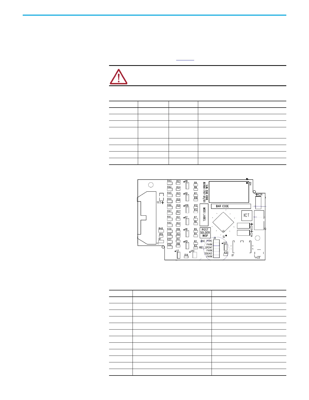
The 80190-759-02 universal encoder interface is functionally identical to the
80190-759-01 with the addition of conformal coating. The universal encoder
interface is configured via jumpers installed on the 12-position header J4. The
header has three positions labeled ‘Park’ and used to store the jumpers when
indicated as “Removed” in the table below. Each function is selected by moving
its corresponding jumper from the ‘park’ location to the selected function
location if labeled “Installed”. Table 14
describes the functions available.
Figure 137 - Universal Encoder Board
Connections to the universal encoder interface occur via a 1492-IFM20F
interface module. The connections to the IFM are detailed below.
ATTENTION: Removing the Universal Encoder Interface with active control
power may damage the board. Disconnect the control power before
removing the board.
Table 14 - Encoder Configurations
ENC_TYPE POL_QRDNT CD_DQUAD CONFIGURATION
Installed Installed Installed Single quadrature encoder option (Factory Default)
Installed Installed Removed Dual quadrature encoder option without redundancy
Installed Removed Removed Dual quadrature encoder option with redundancy
Installed Removed Installed
Single quadrature option (CDSEL/DQUAD) must be
removed for redundancy
Removed Installed Installed Gray code absolute encoder low true
Removed Installed Removed Natural binary absolute encoder low true
Removed Removed Installed Gray code absolute encoder high true
Removed Removed Removed Natural binary absolute encoder high true
Table 15 - Encoder Functions
IFM Pin # Quadrature Encoder Function Absolute Encoder Function
1A1+ E0
2A1- E1
3B1+ E2
4B1- E3
5 ENC_COM ENC_COM
6Z1+ E4
7Z1- E5
8 A2+ (redundant or dual ENC) E6
9 A2- (redundant or dual ENC) E7
10 ENC_COM ENC_COM
11 B2+ (redundant or dual ENC) E8
12 B2- (redundant or dual ENC) E9

 Loading...


