SMIQ Digital Standard PDC
1125.5555.03 E-92.287
(CLOCK...) CLOCK SOURCE
Selection of clock source.
INT SMIQ uses internally generated clock signals.
EXT An external symbol clock or bit clock is fed in at
connectors SYMBOL CLOCK or BIT CLOCK. The
clock synthesizer on the modulation coder is
synchronized to this clock.
The symbol rate has to be set with an accuracy of
± 1 %.
The polarity, the trigger threshold and the input
resistance of the clock inputs can be modified in
menu DIGITAL MOD - EXT INPUTS.
IEC/IEEE-bus command
:SOUR:PDC:CLOC:SOUR INT
MODE
Selection of clock for external clock signal.
SYMBOL The external clock has to be a symbol clock.
BIT The external clock has to be a bit clock.
IEC/IEEE-bus command
:SOUR:PDC:CLOC:MODE SYMB
DELAY
Setting the delay of generated modulation signal to an
external clock.
This can be used, for example, for synchronization with a
second unit to achieve time synchronization between the
modulation signals of the two units.
IEC/IEEE-bus command
:SOUR:PDC:CLOC:DEL 0.5
POWER RAMP
CONTROL...
Opens a window for setting the envelope control, especially for the rising and
falling ramp at the beginning and end of a slot.
FREQ
100. 000 000 0
MHz
FREQUENCY
LEVEL
ANALOG MOD
VECTOR MOD
DIGITAL MOD
DIGITAL STD
LF OUTPUT
SWEEP
LIST
MEM SEQ
UTILITIES
PDC
PHS
IS95
NADC
PDC
GSM
STATE
MODULATION...
TRIGGER MODE
EXECUTE TRIG
TRIGGER....
CLOCK...
POWER RAMP C>
SLOT ATTENUA
0
TCH
SET DEFAULT
RAMP TIME
2 Symb
RAMP FUNCTIOM LIN COS
RAMP DELAY 0.0 Symb
RISE OFFSET 0 Symb
FALL OFFSET 0 Symb
LEVEL
-30.0
dBm
PEP
-27.4
dBm
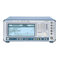
Fig. 2-189 Menu DIGITAL STD - PDC - POWER RAMP CONTROL... , SMIQ equipped with
Modulation Coder SMIQB20 and Data Generator SMIQB11
 Loading...
