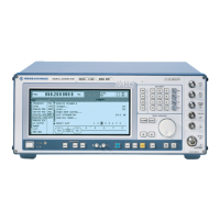
Basic Operating Steps SMIQ
1125.5555.03 E-82.22
2.2 Basic Operating Steps
The operating principle is explained in this section. For better understanding, please read section
"Sample Setting for First Users" (Section 2.2.10) in addition.
To operate the instrument, menus are called in the display. All setting possibilities and the current
setting status are evident from the menus. All settings can be made by accessing the menus.
RF frequency and RF level can also be set without menu operation using keys [FREQ] and [LEVEL].
RF signal and modulation can also be switched on/off without menu operation using keys [RF ON/OFF]
and/or [MOD ON/OFF].
2.2.1 Design of the Display
AM
BB-AM
FM
PM
PULSE
FREQ
100. 000 000 0
MHz
LEVEL
- 30.0
dBm
FM1 DEVIATION
FM1 SOURCE
LFGEN FREQ
FM2 DEVIATION
FM2 SOURCE
EXT1 COUPLING
EXT2 COUPLING
PREEMPHASIS
FM
1.00 kHz
OFF INT EXT1 EXT2
1.000 0 kHz
10.0 kHz
OFF EXT1 EXT2
AC DC
AC DC
OFF 50µ 75µ s
1
2
3
Main menu
Submenu
Setting menu
1 Header field
2 Status line
3 Menu fields
Menu cursor
Digit cursor
Select mark
FREQUENCY
LEVEL
ANALOG MOD
VECTOR MOD
DIGITAL MOD
DIGITAL STD
LF OUTPUT
SWEEP
LIST
MEM SEQ
UTILITIES
Fig. 2-3 Design of the display
Header field
(1)The header field of the display indicates frequency and level of the RF output signal
which considers the offset value. In the RF-sweep operating mode, the start and stop
frequencies are displayed in two lines one above the other. The start and stop levels
are indicated in the LEVEL-sweep operating mode correspondingly. A two-line level
display appears for digital modulation or digital standard. The upper line indicates the
average power (LEVEL), the lower line the peak envelope power (PEP) of the
modulated RF output signal.
Status line
(2) The status line below describes operating mode and operating state of the instrument.
Error messages and notes for caution are also displayed in the status line.

 Loading...