23
Part Names and Functions
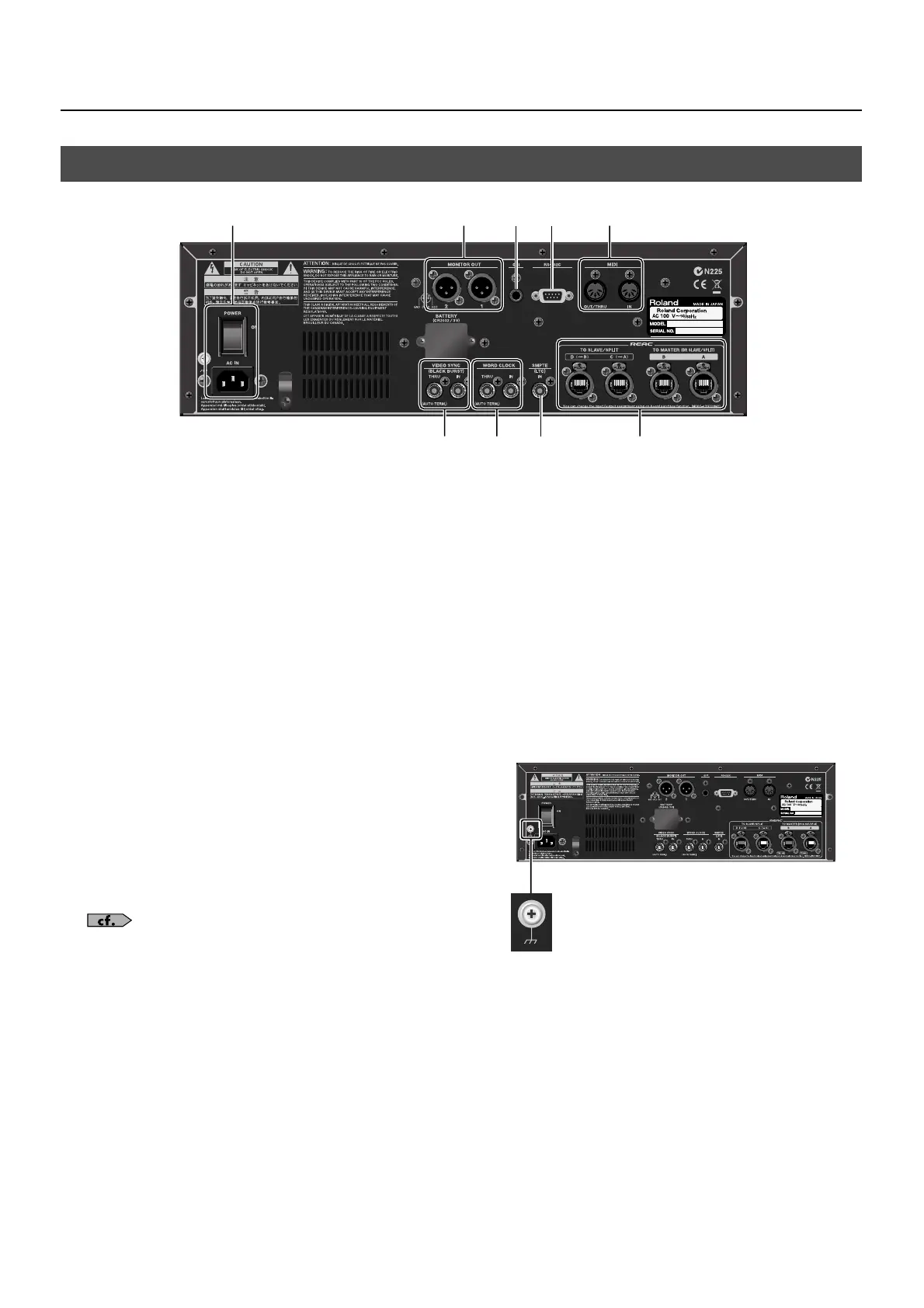
fig.rear-panel.eps
1. AC IN Connector and POWER Button
Connect the included power cord here. Use the POWER
switch to turn the R-1000 on and off.
2. MONITOR OUT Connectors
Connect monitor speakers here. A mono mix of all channels
and tracks is output.
* The same mono audio is output from the [1] and [2] connectors.
3. GPI Connector
Connect foot switches and devices capable of GPI output
here.
4. RS-232C Connector
Connect a computer or other equipment capable of RS-232C
serial output here.
5. MIDI Connectors
You can remote control recording, playback, and other
operations from an external MIDI device.
For information on operating the unit remotely from a GPI, RS-232C,
or MIDI device, refer to “About Remote Control” (p. 73).
6. VIDEO SYNC Connectors
When you are synchronizing the R-1000 with a video source,
connect a black-burst generator or other source here.
* For thru-out, use the [THRU] connector.
7. WORD CLOCK Connectors
For synchronization to an external sampling clock, connect
the word-clock generator or other sampling-clock source
here.
* For thru-out, you use the [THRU] connector.
8. SMPTE Connector
For synchronization to an SMPTE timecode, connect a
timecode generator here.
9. REAC Connectors
Connect a digital snake device, V-Mixer, and other REAC
devices here. For information on how to make the
connections, refer to “Connecting REAC Devices” (p. 24).
About Functional Ground Terminal
You can use the ground terminal shown below to connect
the unit to an external ground in order to eliminate ground-
related noise problem.
fig.earth-terminal.eps
However, never connect the unit to any of the following
locations.
• Water pipes (may result in shock or electrocution)
• Gas pipes (may result in fire or explosion)
• Telephone-line ground or lightning rod (may be dangerous in the
event of lightning)
Rear Panel
1 2
3
5
6 7 89
4
 Loading...