Technical data
RES-445 Page 11
Analog output
(actual value)
Terminals 20+24
0…10VDC, Imax = 5mA
Equivalent to 0…300°C or 0…500°C
Electrically isolated
Accuracy: ±1% add. 50mV
Digital logic levels
Terminals 3, 4, 22, 25,
26
LOW (0V): 0…2VDC
HIGH (24VDC): 12…30VDC (max. current input 6mA)
Electrically isolated, reverse polarity-protected
START with contact
Terminals 2+7
Switching threshold: 3.5VDC, U
max
= 5VDC, I
max
=5mA
Switching output
for „"Output 1"/
Temp. OK" signal
Terminals 20+21
U
max
= 30VDC, I
max
=50mA
U
ON
< 2V (saturation voltage)
Transistor conductive if the temperature is inside the tolerance band.
Alarm relay
Terminals 5+6
Contact, potential-free, U
max
= 50V (DC/AC), I
max
=0.2A
Relay K1
Terminals 16, 17, 18
Changeover contact, potential-free, U
max
= 240VAC/100VDC, I
max
=1.5A
Interference suppression with 47nF / 560ohms for each terminal
Maximum load
(primary current of
impulse transformer)
I
max
= 5A (duty cycle = 100%)
I
max
= 25A (duty cycle = 20%)
Power dissipation max. 25W
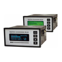
Display LC display (green), 4 lines, 20 characters, alternatively:
VF display (blue), 4 lines, 20 characters
Ambient temperature +5…+45°C
Degree of protection Front: IP42 (IP65 with transparent front cover, Art. No. 887000)
Back: IP20
Installation Installed in front panel cutout with (W x H) 138
(+-0.2)
x68
(+-0.2)
mm
Fastened with clips
Weight Approx. 1.0kg (incl. connector plug-in parts)
Housing material Black plastic, type Noryl SE1 GFN2
Connecting cable
Type / cross-sections
Rigid or flexible; 0.2…2.5mm² (AWG 24…12)
Plug-in connectors
If ferrules are used, they must be crimped in accordance
with DIN 46228 and IEC/EN 60947-1.
This is essential for proper electrical contact in the terminals.