Controller functions
RES-445 Page 59
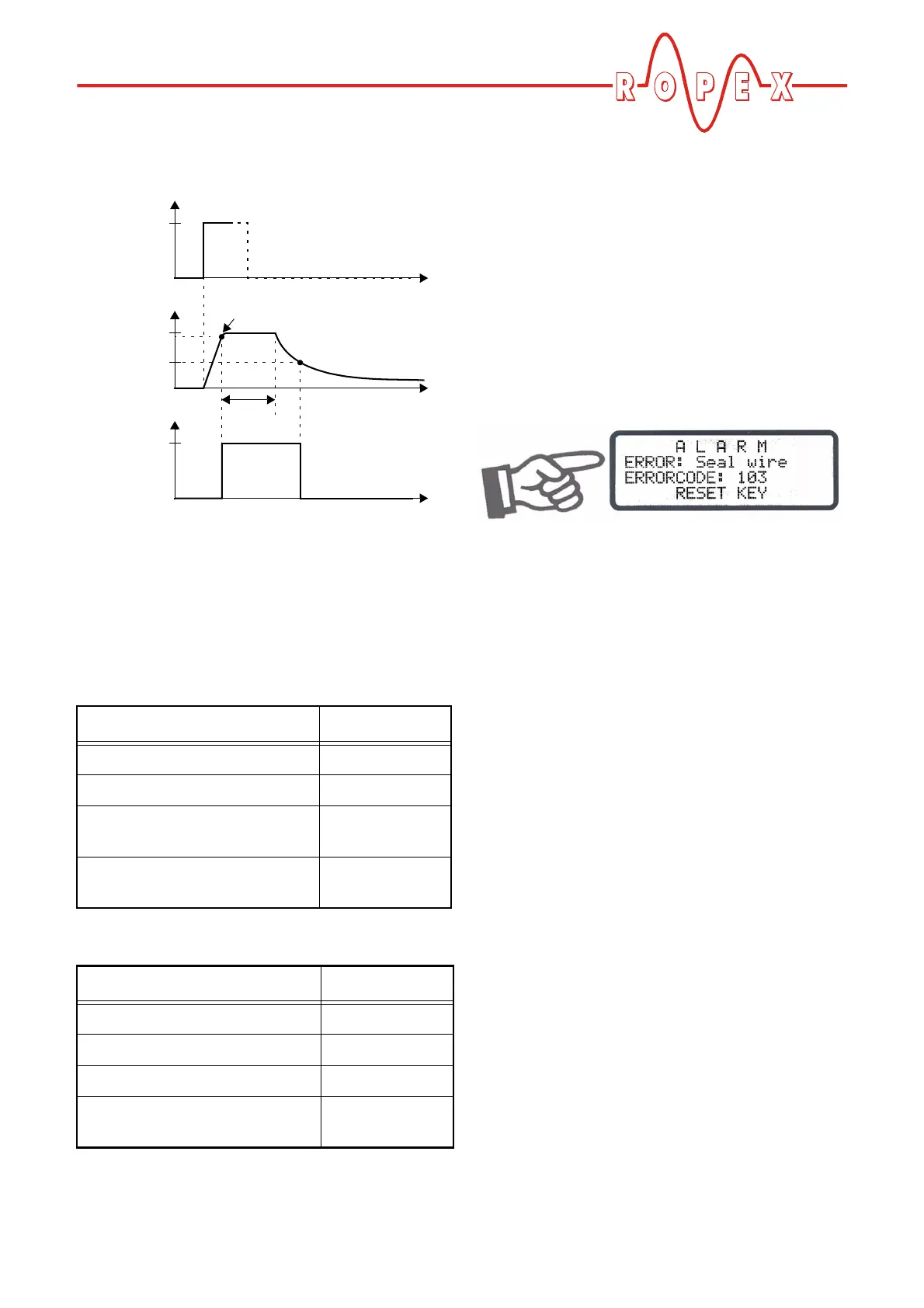
The timing sequence can be represented as follows:
Required controller settings:
The following controller settings are required for time
control (the basic settings such as the temperature
range, alloy etc. should already have been entered).
The settings should be undertaken in the specified
order.
Then:
10.25 System monitoring/alarm output
To increase operating safety and to avoid faulty heatse-
aling, the controller incorporates special hardware and
software features that facilitate selective fault detection
and diagnosis. Both the external wiring and the internal
system are monitored.
These features crucially support the system owner in
localizing the cause of an abnormal operating state.
A system fault is reported or differentiated by means of
the following elements.
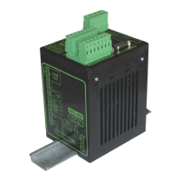
A.) Error message on the display:
The cause of a fault can be localized quickly and easily
with the help of the error code that appears on the dis-
play. Please refer to section 10.27 "Fault areas and
causes" on page 64 for a list of the possible error
codes.
B.) Alarm relay (relay contact, terminals 5+6):
This contact is set in the factory as follows:
• OPEN if error code 104…106, 111…113 or 211 is
displayed. The contact closes, however, if a
"START" signal is activated in this state.
• CLOSED if error code 101…103, 107, 108,
201…203, 801 or 9xx appears.
If the alarm relay is configured differently from the fac-
tory setting ( section 9.3.12 "Configuration of the
alarm relay" on page 25), these states are inverted.
C.) Error code output via the 0 to 10VDC
actual value output (terminals 20+24):
Since a temperature indication is no longer necessary
if a fault occurs, the actual value output is used to dis-
play error codes in the event of a fault.
13 voltage levels (up to software revision 027:
12 voltage levels) are offered for this purpose in the
0…10VDC range, each of which is assigned an error
code ( section 10.27 "Fault areas and causes" on
page 64).
If a state that requires AUTOCAL occurs – or if the con-
troller configuration is incorrect – (error codes
104…106, 111…113 or 211), the actual value output
Step in Configuration menu Setting
26 (Time control) "ON"
27 (Cooling mode) "Absolute"
28 (Start of heatsealing time) "When temp.
reached"
29 (Relay K1 function) "When temp.
reached"
Step in Settings menu Setting
101 [1] (Heatsealing temp.) 180°C
103 [3] (Starting delay) 0.0 s
104 [4] (Heatsealing time) 1.0 s
105 [5] (Cooling value) Cooling
temp. = 80°C
ACT temperature
START signal (foot switch)
180°C
t
t
0
0
80°C
1s
t
Open
NO contact of
Closed
relay K1
95% of 180°C