Page 2 RES-445
Contents
1 Safety and warning notes . . . . . . . . . . . . . . 4
1.1 Use . . . . . . . . . . . . . . . . . . . . . . . . . . . 4
1.2 Heatsealing band . . . . . . . . . . . . . . . . 4
1.3 Impulse transformer . . . . . . . . . . . . . . 4
1.4 Current transformer PEX-W2/-W3 . . . . 4
1.5 Line filter . . . . . . . . . . . . . . . . . . . . . . . 5
1.6 Warranty provisions . . . . . . . . . . . . . . . 5
1.7 Standards / CE marking . . . . . . . . . . . 5
2 Application . . . . . . . . . . . . . . . . . . . . . . . . . . 5
3 Principle of operation . . . . . . . . . . . . . . . . . 6
4 Description of the controller . . . . . . . . . . . 7
5 Accessories and modifications . . . . . . . . . 7
5.1 Accessories . . . . . . . . . . . . . . . . . . . . . 7
5.2 Modifications (MODs) . . . . . . . . . . . . . 9
6 Technical data . . . . . . . . . . . . . . . . . . . . . . 10
7 Dimensions/front panel cutout . . . . . . . . . 12
8 Installation . . . . . . . . . . . . . . . . . . . . . . . . . 13
8.1 Installation procedure . . . . . . . . . . . . 13
8.2 Installation steps . . . . . . . . . . . . . . . . 14
8.3 Power supply . . . . . . . . . . . . . . . . . . . 15
8.4 Line filter . . . . . . . . . . . . . . . . . . . . . . 16
8.5 Current transformer PEX-W3 . . . . . . 16
8.6 Wiring diagram (standard) . . . . . . . . . 17
8.7 Wiring diagram with booster
connection . . . . . . . . . . . . . . . . . . . . . 18
9 Startup and operation . . . . . . . . . . . . . . . . 19
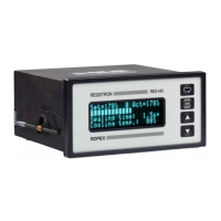
9.1 Front view of the controller . . . . . . . . 19
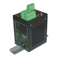
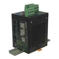
9.2 Rear view of the controller . . . . . . . . . 19
9.3 Controller configuration . . . . . . . . . . . 20
9.4 Heatsealing band . . . . . . . . . . . . . . . 25
9.5 Startup procedure . . . . . . . . . . . . . . . 26
10 Controller functions . . . . . . . . . . . . . . . . . 27
10.1 Indicators and controls . . . . . . . . . . . 27
10.2 Display . . . . . . . . . . . . . . . . . . . . . . . . 28
10.3 Navigation in the menus . . . . . . . . . . 29
10.4 Menu structure . . . . . . . . . . . . . . . . . . 31
10.5 Two-digit numbering system
up to software revision 027 . . . . . . . . 33
10.6 Menu steps . . . . . . . . . . . . . . . . . . . . 34
10.7 Temperature setting (set point
selection) . . . . . . . . . . . . . . . . . . . . . . 43
10.8 Temperature indication/actual value
output . . . . . . . . . . . . . . . . . . . . . . . . . 44
10.9 Automatic zero calibration
(AUTOCAL) . . . . . . . . . . . . . . . . . . . . 45
10.10 "START" signal (HEAT) . . . . . . . . . . . 46
10.11 "PREHEAT" signal
(preheating) . . . . . . . . . . . . . . . . . . . . 47
10.12 "RESET" signal . . . . . . . . . . . . . . . . . 48
10.13 Cycle counter . . . . . . . . . . . . . . . . . . . 48
10.14 Hold mode . . . . . . . . . . . . . . . . . . . . . 49
10.15 Measuring impulse duration
(as of software revision 026) . . . . . . . 50
10.16 Automatic phase angle
compensation (AUTOCOMP)
(as of software revision 100) . . . . . . . 50
10.17 Locking the "HAND" key
(as of software revision 100) . . . . . . . 50
10.18 Temperature unit
Celsius / Fahrenheit
(as of software revision 106) . . . . . . . 51
10.19 Disabling the Configuration menu . . . 51
10.20 Setting the display brightness
(VF display only) . . . . . . . . . . . . . . . . 51
10.21 Undervoltage detection . . . . . . . . . . . 52
10.22 Diagnostic interface/visualization software
(as of software revision 100) . . . . . . . 52
10.23 Booster connection . . . . . . . . . . . . . . 52
10.24 Time control (timer function) . . . . . . . 53
10.25 System monitoring/alarm output . . . . 59
10.26 Error messages . . . . . . . . . . . . . . . . . 60
10.27 Fault areas and causes . . . . . . . . . . . 64
11 Factory settings . . . . . . . . . . . . . . . . . . . . . 65
11.1 Customer settings
(as of software revision 100) . . . . . . . 67