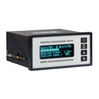
Startup and operation
Page 26 RES-445
9.5 Startup procedure
Please also refer to Kap. 1 „Safety and warning notes“
auf Seite 4 and Kap. 2 „Application“ auf Seite 5.
Installation and startup may only be per-
formed by technically trained, skilled per-
sons who are familiar with the associated risks and
warranty provisions.
9.5.1 Initial startup
Prerequisites: The controller must be correctly installed
and connected ( Kap. 8 „Installation“ auf Seite 13).
The possible settings are described in detail in
chap. 9.3 „Controller configuration“, page 20 and
chap. 10 „Controller functions“, page 27.
The essential controller configurations are described
below:
1. Switch off the line voltage and verify that all circuits
are deenergized.
2. The supply voltage specified on the nameplate of
the controller must be identical to the line voltage
that is present in the plant or machine. The line fre-
quency is automatically detected by the tempera-
ture controller in the range from 47 to 63Hz.
3. In case of controllers up to software revision 027,
the setting of the DIP switches on the controller are
indicated in the ROPEX Application report and
depend on the heatsealing band (section 9.3 "Con-
troller configuration" on page 20).
4. Make sure that a START signal is not present.
5. Switch on the line voltage.
6. A power-up message appears on the display for
approximately 2 seconds when the controller is
switched on to indicate that it has been started up
correctly.
7. One of the following states then appears:
8. Set the controller configuration as described in
Kap. 9.3 „Controller configuration“ auf Seite 20. The
following settings are always required:
9. Activate the AUTOCAL function while the heatse-
aling band is still cold (with step 7 in the Settings
menu or by means of the "AUTOCAL" signal, termi-
nals 20+25). The progress of the calibration process
is indicated by a counter on the display (approx.
10…15s). A voltage of app. 0VDC appears at the
same time at the actual value output (terminals
20+24). If an ATR-x is connected, it indicates
0…3°C.
When the zero point has been calibrated, the dis-
play is reset to the home position and 20°C is indi-
cated as the actual value. A voltage of 0.66VDC (for
the 300°C range) or 0.4VDC (for the 500°C range,
equivalent to 20°C, appears at the actual value
output. If an ATR-x is connected, it must be set to "Z"
(20°C).
If the zero has not been calibrated successfully, an
erro message indicates error codes 104…106, 211.
In this case the controller configuration is incorrect
( Kap. 9.3 „Controller configuration“ auf Seite 20
and ROPEX Application Report). Repeat the zero
point calibration after the controller has been confi-
gured correctly.
10.When the zero point has been calibrated suc-
cessfully, the main menu appears on the display
again. Then specify a defined temperature (heatse-
aling temperature) with step 1 in the Settings menu
(or apply a 0…10VDC voltage to the analog input,
terminals 20+23) and activate the "START" signal
(HEAT). Alternatively, a heatsealing process can be
started by pressing the "HAND" key (display in
home position). The indication of the ACTUAL tem-
perature on the display (digital value and dynamic
bar) permits the heating and control process to be
monitored.
The controller is functioning correctly if the tempera-
ture indicated on the display has a continuous
curve, in other words it must not jump abruptly, fluc-
tuate or deviate temporarily in the wrong direction.
This kind of behavior would indicate that the U
R
measuring wire has been laid incorrectly.
If an error code is displayed, please proceed as
DISPLAY ACTION
Main menu Go to 8
Error message with error codes
104…106, 111…113, 211
Go to 8
Error message with error codes
101…103, 107, 108,
201…203, 801, 9xx
Fault diagnosis
( 10.27)
Setting
Step in Confi-
guration menu
Language 201 [20]
Restore factory settings 202 [21]
Temperature range and heatse-
aling band alloy
203, 204, 205
[22]