Controller functions
Page 64 RES-445
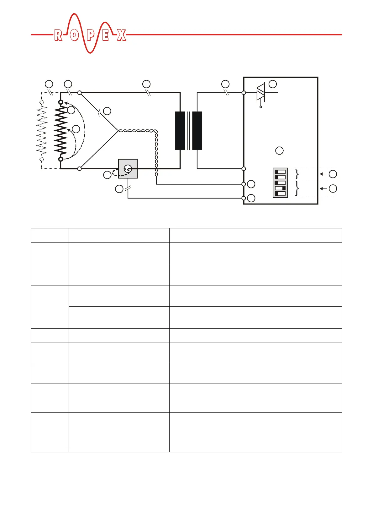
10.27 Fault areas and causes
The table below explains the possible fault causes.
Temperature
8
7
UR
IR
U2
I2
32
1
45
7
8
Fault area Explanation Possible causes
Load circuit interrupted after U
R
pickoff point
- Wire break, heatsealing band break
- Contacting to heatsealing band defective
PEX-W2/W3 current transformer
signal interrupted
-I
R
measuring wire from current transformer interrupted
Primary circuit interrupted
- Wire break, triac in controller defective
- Primary winding of impulse transformer interrupted
Secondary circuit interrupted
before U
R
pickoff point
- Wire break
- Secondary winding of impulse transformer interrupted
U
R
signal missing
- Measuring wire interrupted
Partial short-circuit (delta R)
- Heatsealing band partially bypassed by conducting part
(clamp, opposite heatsealing bar etc.)
Parallel circuit interrupted
- Wire break, heatsealing band break
- Contacting to heatsealing band defective
Total short-circuit
- Heatsealing band installed incorrectly, insulation at heatse-
aling bar ends missing or incorrectly installed
- Conducting part bypasses heatsealing band completely
U
R
signal incorrect
- Up to software revision 027: DIP switches 1 - 3 configured
incorrectly (U
2
range)
- As of software revision 100: U
2
outside permissible range
from 0.4…120VAC