Controller functions
Page 60 RES-445
jumps back and forth at 1Hz between the voltage value
that corresponds to this error and the end of the scale
(10VDC, i.e. 300°C or 500°C). If the "START" signal is
activated in one of these states, the voltage value does
not change any more.
Selective fault detection and indication can thus be
implemented simply and inexpensively using the
analog input of a PLC with a corresponding error mes-
sage ( section 10.27 "Fault areas and causes" on
page 64).
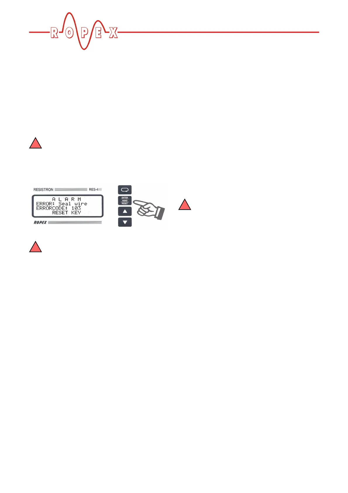
An error message can be reset by pressing
the "RESET" key, by activating the "RESET"
signal at terminals 20+26 ( section 10.12
""RESET" signal" on page 48) or by switching the
controller off and then on again.
Invalid error messages may appear when the
controller is switched off owing to the unde-
fined operating state. This must be taken into
account when they are evaluated by the higher-
level controller (e.g. a PLC) in order to avoid false
alarms.
10.26 Error messages
The table below shows how the analog voltage values
that appear at the actual value output correspond to the
faults that have occurred. It also describes each fault
and the required corrective action. The block diagram
in section 10.27 "Fault areas and causes" on page 64
permits each fault to be cleared quickly and efficiently
The error codes described below can also be displayed
in the ROPEX visualization software ( section 10.22
"Diagnostic interface/visualization software (as of soft-
ware revision 100)" on page 52) to facilitate troubles-
hooting.
If the actual value output is evaluated in order
to identify an error message - in the higher-
level controller, for instance - the tolerance window
must be adjusted to prevent it from being incor-
rectly interpreted. Please note the tolerances of the
actual value output ( section 6 "Technical data"
on page 10).