Startup and operation
Page 20 RES-445
Up to software revision 027:
9.3 Controller configuration
The possible controller configurations are explained in
the following sections. Proceed as described in
Kap. 9.5.1 „Initial startup“ auf Seite 26 to start up the
controller for the first time.
9.3.1 Configuration of the DIP switches
for secondary voltage and current
The controller must be switched off in order
to configure the DIP switches.
Automatic configuration (AUTORANGE
)
(as of software revision 100)
The secondary voltage and current ranges are auto-
matically configured by the automatic calibration func-
tion (AUTOCAL). The voltage is configured in the range
from 0.4VAC to 120VAC and the current in the range
from 30A to 500A. If the voltage and/or the current is
outside the permissible range, a detailed error mes-
sage appears on the controller ( s. section 10.27
"Fault areas and causes" on page 64).
Configuration with coding switches
(up to software revision 027)
Set the DIP switches for matching the secondary
voltage U
2
and the secondary current I
2
to the correct
position for your application.
You can find the exact configuration of the
DIP switches in the ROPEX Application
Report calculated for your particular application.
1234567891011
19 20 21 22 23 24 25 26
32145
18
17
16
12 3 45
ROPEX
19 20 21 22 23 24 25 26
U (
V
)
2
I
2
(
A
)
1-10 6-60 20-120
30 - 100
60 - 200
120 - 400
OFF
OFF
OFF
ON
ON
ON
DIP-SWITCH
ON
1
16 17 18
K1
U
1
4567891011
12 13 14
15
PRIM.
START
24VDC
START
Contact
CH1
Contact
50V / 0,2A
BOOSTER ALARM
GND
FILTER
N (L1)
(only with filter)
U
2
TEMP. OUT
0 - 10VDC
RESET
MP. IN
10VDC
CH1
4VDC
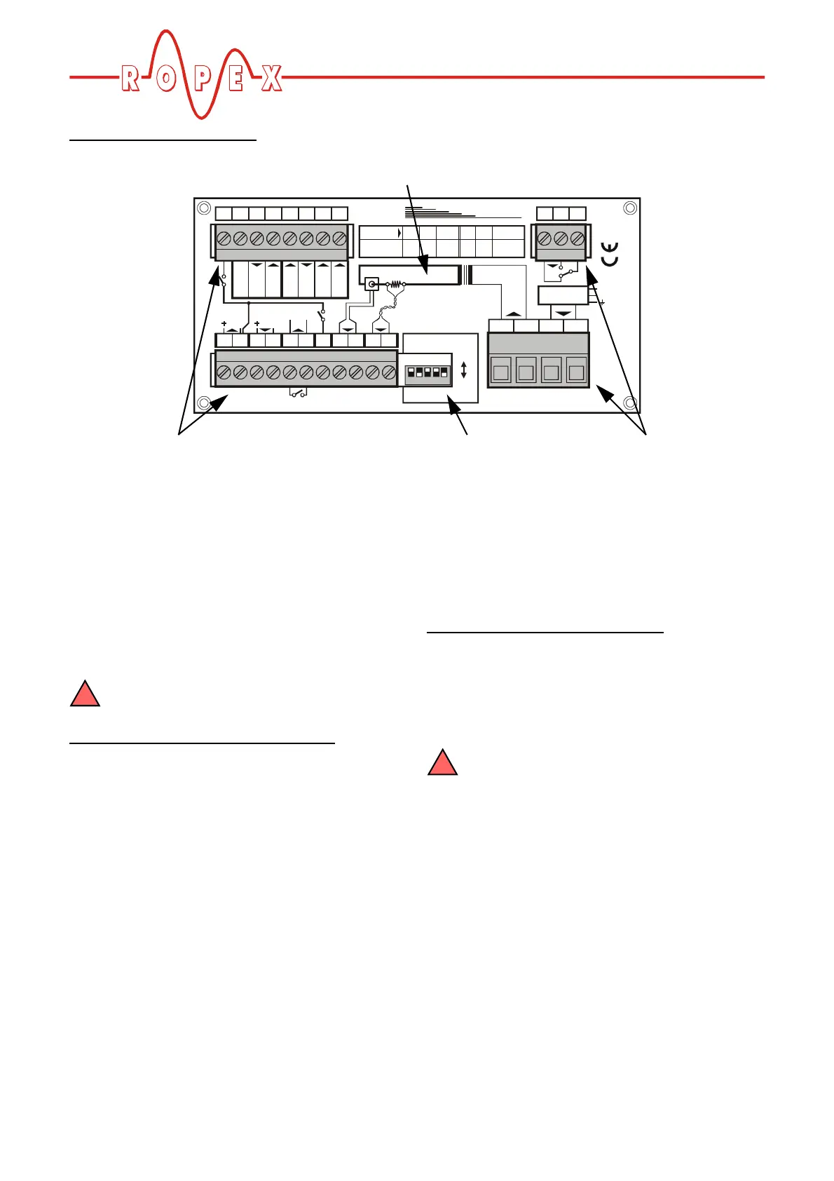
Printed wiring diagram
Terminals DIP switches Terminals