Controller functions
Page 48 RES-445
The ACTUAL temperature shows whether the heatse-
aling band is heated up to the preheating temperature
correctly, providing the display is in the home position.
Please note the following if the "PREHEAT" func-
tion is used and the temperature is selected via the
analog input at terminals 20+23:
The voltage at the analog input is valid for the prehea-
ting temperature and the heatsealing temperature. Pre-
heating cannot be activated with the "PREHEAT"
signal in conjunction with the analog input.
If this function is used, the preheating temperature
must be set by altering the voltage value at the analog
input. The "START" signal is always activated for this
purpose (the "PREHEAT" signal is deactivated).
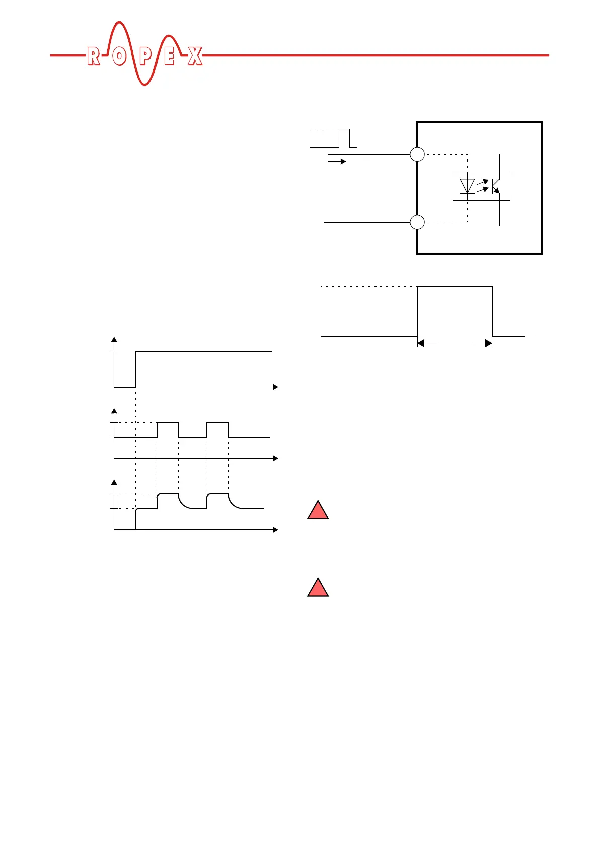
The timing sequence is shown in the diagram below:
10.12 "RESET" signal
The RESISTRON temperature controller RES-445 can
be reset by means of an external "RESET" signal at ter-
minals 20+26.
As a result:
• A heatsealing cycle is aborted if one is in progress
• No more measuring impulses are generated
• An error message is reset if one is present
The actual value output changes to 0…3°C (i.e. appro-
ximately 0VDC) while the "RESET" signal is being acti-
vated. This may be interpreted by the higher-level con-
troller (e.g. a PLC) as feedback.
The message "External RESET signal active" is addi-
tionally displayed on the controller as of software
revision 009 when the "RESET" signal is active.
The "AUTOCAL" function is not aborted if the "RESET"
signal is activated while it is still executing.
The controller executes an internal initializa-
tion for approximately 500ms after the
"RESET" signal is deactivated. The next heatse-
aling process cannot be started until it has fini-
shed.
If a contactor Kb is used to deactivate the
control loop ( Kap. 8.3 „Power supply“ auf
Seite 15), it must be energized again 50ms at the
latest after the "RESET" signal is deactivated. If it is
energized too late, an error message will be output
by the controller.
10.13 Cycle counter
Each activation of the "START" signal during operation
is detected by a cycle counter integrated in the con-
troller. Actuations of the "HAND" key are not counted.
The counter reading can be displayed with
step 214 [30] in the Configuration menu.
"START"
signal
ACTUAL
temp.
Voltage at
anal. input
24VDC
T
2
T
1
T
1
= Preheating temperature (corresponds to
U
1
)
t
t
t
0
0
0
U
2
U
1
RES-445
max. 6mA
26
20
RESET
+
-
GND
24VDC
RESET
>0.1s
HIGH:
12VDC
LOW:
2VDC