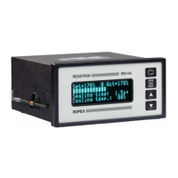
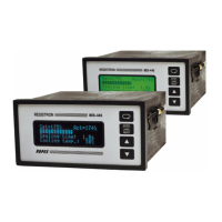
Controller functions
Page 52 RES-445
10.21 Undervoltage detection
Trouble-free operation of the temperature controller is
guaranteed within the line voltage tolerance range spe-
cified in section 6 "Technical data" on page 10.
If a line voltage which is less than the lower limit of the
permissible range occurs, the controller is switched to
a standby mode. No more heatsealing processes take
place and no more measuring impulses are generated.
The display changes to indicate this.
The main menu is displayed again, and operation is
resumed, when the input voltage returns to the speci-
fied tolerance range.
The alarm relay (terminals 5+6) is only switched by an
undervoltage condition in controllers up to and inclu-
ding software revision 002. The last valid temperature
value continues to appear at the analog output (termi-
nals 20+24).
The alarm relay in controllers with a higher software
revision number is not switched if an undervoltage con-
dition occurs. The standby mode is indicated by 0…3°C
(corresponds to app. 0V) at the analog output.
Trouble-free operation of the controller is
only guaranteed within the specified input
voltage tolerance range. An external voltage
monitor must be connected to prevent defective
heatseals as a result of low line voltage.
10.22 Diagnostic interface/visualization
software
(as of software revision 100)
An interface with a 6-pole Western socket is provided
for systemdiagnostics and process visualization. This
interface allows a data connection to be set up to the
ROPEX visualization software using the ROPEX com-
munication interface CI-USB-1.
Only a ROPEX comunication interface is
allowed to be connected to the diagnostic
interface. Connecting another device (e.g. a tele-
phone cable) could result in malfunctions or
damage to the controller.
The ROPEX visualization software is described in a
separate document.
10.23 Booster connection
The RES-445 controller has a connection for an
external switching amplifier (booster) as standard. This
connection (at terminals 1+2) is necessary for high pri-
mary currents (continuous current > 5A, pulsed
current > 25A). The switching amplifier should be con-
nected as described in section 8.7 "Wiring diagram with
booster connection" on page 18. No settings are
required in the menu.
12
R
U
R
I
Back view of the controller