Controller functions
RES-445 Page 53
10.24 Time control (timer function)
10.24.1 Activation and indication
The settings described here are only allowed
to be entered by technically trained persons.
An incorrectly parameterized timer function may
cause disruptions to operation and damage to the
machine.
The timer function is activated with step 209 [26] in the
Configuration menu. There are two possible settings in
this menu:
1. "OFF" (Factory setting)
Time control (timer function) deactivated
2. "ON"
Time control (timer function) activated.
The internal timeout is started by activating the
"START" signal. The timeout either ends with the
parameterized cooling phase or is interrupted by
activating the "RESET" signal.
3. "ON with START monitoring"
(Software revision 021 or higher)
Time control (timer function) activated and "START"
signal monitored.
Once again, the internal timeout is started by acti-
vating the "START" signal. In this setting, however,
the "START" signal must remain activated until the
end of the parameterized cooling phase. If the
"START" signal is deactivated before the end of the
cooling phase - or if the "RESET" signal is
activated - the timeout is interrupted.
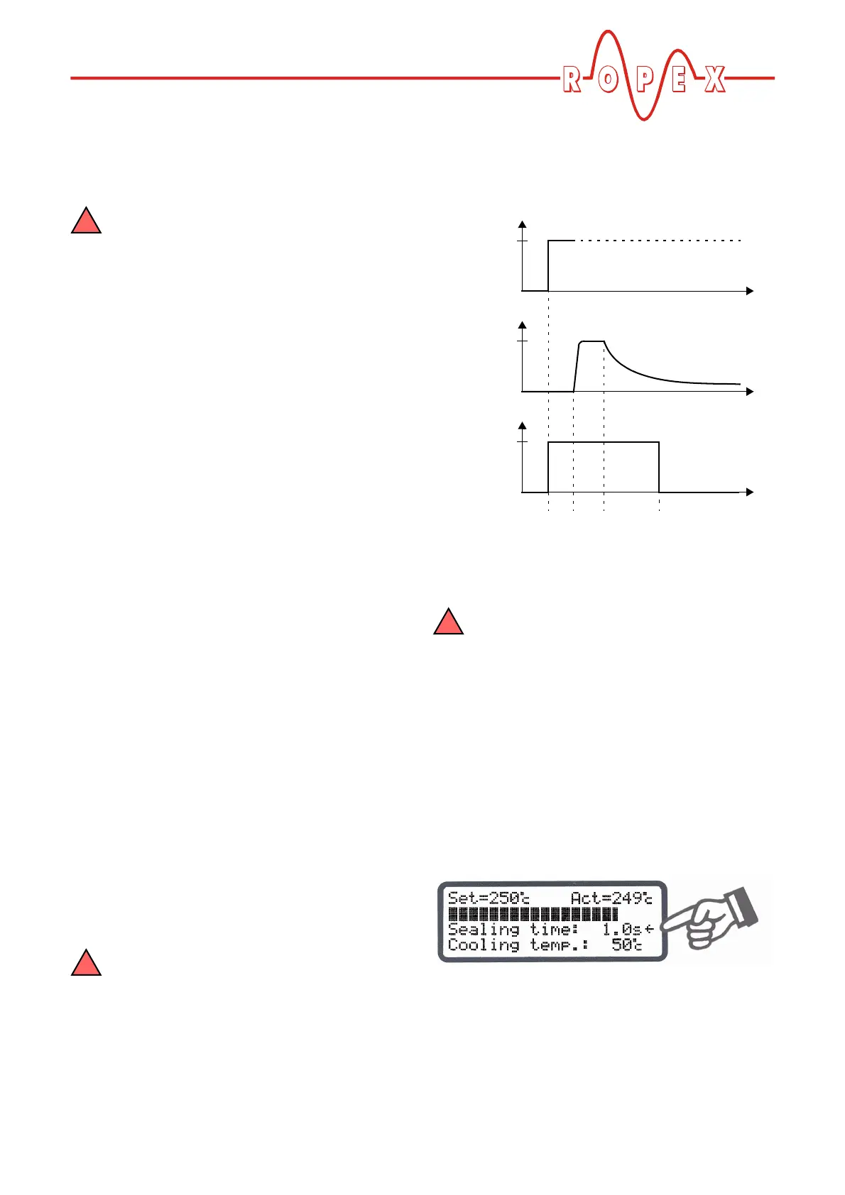
If time control is on, activating the "START" signal starts
the internally parameterized timeout. This timeout com-
prises:
• Starting delay (delay at the beginning of the heating
phase)
• Heating phase (heating and control process)
• Cooling phase
• Relay K1 function
If time control (timer function) is activated, it
is only possible to start a heating process
with the "HAND" key on the controller. The timeout
of the internal time control cannot be started with
this key.
The timeout of the internal time control (timer
function) can be interrupted by activating the
external "RESET" signal (software revision 009 or
higher) or by switching off the controller. As of soft-
ware revision 021, it can also be interrupted by
deactivating the "START" signal if time control "ON
with START monitoring" is configured.
If the display is in the home position, the individual
timeouts can be monitored there.
The remaining heatsealing time is indicated on the dis-
play in the form of a countdown at the end of the hea-
ting phase. A direction arrow indicates the active pro-
cess.
ACTUAL
temp.
START
signal
24VDC
T
t
t
0
0
Relay K1
(example)
t
0
t
1
t
2
t
3
closed
t
1
= Starting delay
t
2
= Heating phase
t
3
= Cooling phase