Rosen Aviation Remote Display System
Revision: A
Date: 04/24/12
Template: 4.2.3-6-FM; Revision A; 16 May, 2005
4. ASSEMBLY INSTRUCTIONS FOR COSMETIC COMPONENTS
This section provides instructions about how to assemble the cosmetic backs and bezels.
Note: Protect cosmetic and sensitive components from scratches, nicks, and debris during
hardware installation.
To add a stylish, proud-mount option, mount the cosmetic back to the bulkhead, attach the RDM to
the cosmetic back, and then snap on the bezel. Figure 15 shows an exploded view of a proud-
mount assembly. Align the four tabs on the monitor with the four mounting brackets on the
cosmetic back plate. Secure with two 4-40 fasteners in each tab/bracket. For more dimensional
information, see Section 3, Installation Guidelines, or the drawing for your specific assembly.
Figure 15 RDM with a proud-mount bezel assembly
4.1. Mounting Cosmetic Backs to a Bulkhead
There are two styles of mounting brackets on the cosmetic backs depending on the size of RDM
that you are installing. The cosmetic backs are a universal fit—there is no top or bottom.
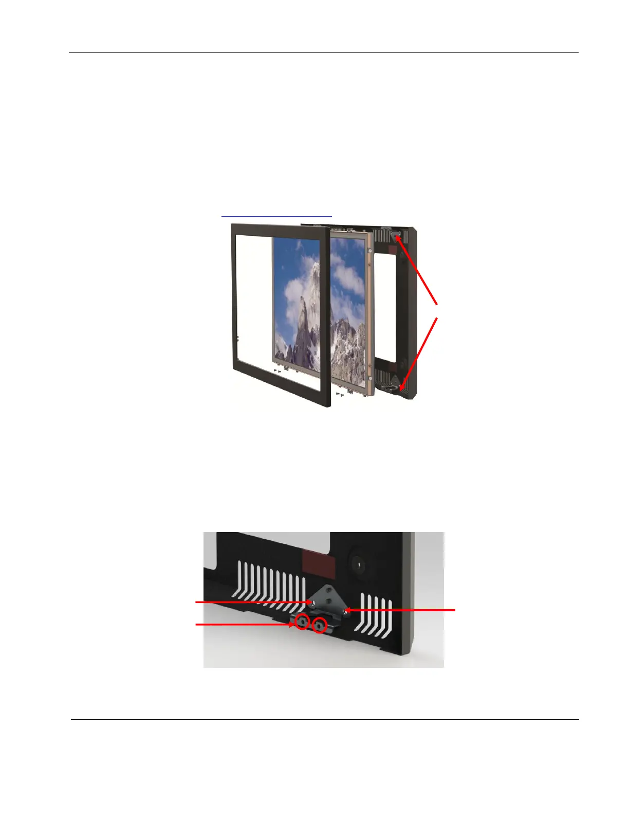
Attach the 19”, 24”, and 26” cosmetics back to the bulkhead using the four mounting
brackets and minimum of four FHP screws (customer supplied) in the .188 mounting
holes, as shown below.
Figure 16 1901-, 2401-, and 2601-800 cosmetic back mounting tabs
Mounting brackets
on the cosmetic
back plate
 Loading...