Rosen Aviation Remote Display System
Revision: A
Date: 04/24/12
Template: 4.2.3-6-FM; Revision A; 16 May, 2005
7. INITIAL POWER UP
Make sure that power is turned off and connect the following harnesses to the RMEB connectors:
1. Ensure positive ground connections on the RMEB housing and monitor chassis
grounding lugs.
2. Connect an external IR control or RS-232/RS-485 communication harness to P1.
3. Connect 28VDC power to P2.
4. Attach extra cabling length (50 feet max.) to the RDM DB 15 pigtail and connect to P3.
5. Attach extra Siemon ZM6A-S(xx)-(xx) cabling (50 feet max.) to the RDM RJ-45 pigtail
and connect to P4. Ground and strain relieve harnesses on RJ-45 connectors using
the brackets provided.
6. Connect the available video inputs.
7. Apply power and wait for a signal on the RDM. The default setting for the RMEB is
Auto On and the default source is SDI 1.
Do not plug or unplug the display connector while power is
applied.
When cycling power, leave unit off for 20 seconds before restoring
power.
8. OSD MENU OPTIONS
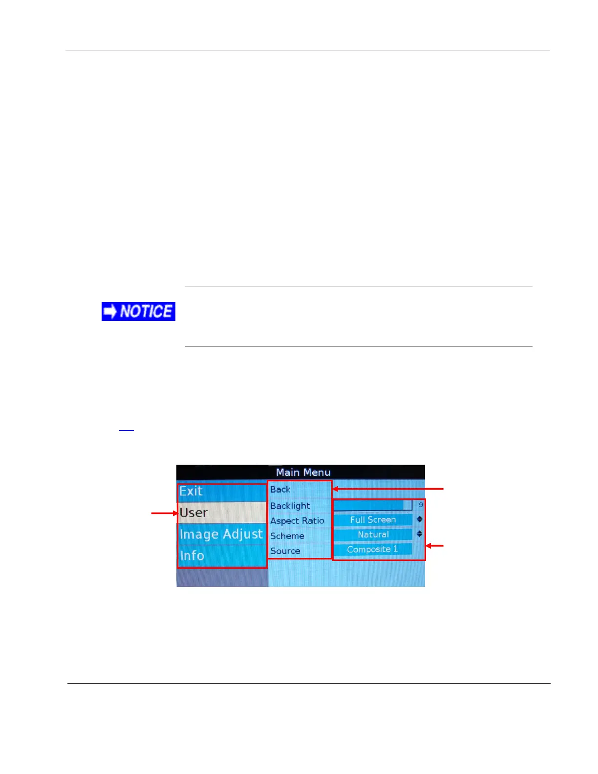
The OSD contains screen settings and options in menus and informational readouts that display
over the image, as shown below. Press MENU on the remote to open the Main Menu, as shown in
Section 8.1. Press the ▲▼ buttons to navigate within the menu pages. Press the ►◄ buttons to
navigate between the menu page, options, and values columns. The yellow highlighted area
shows the currently selected option in the menu.
Figure 21 OSD menu options
The available menu options will vary depending on which source signal is active.
Press MENU to choose a setting or an option.
Select the Back option to switch menu pages.
Press EXIT to close the OSD and save settings.
Press ► to access
the menu page
options
Press ► to access
the menu option
values
Press ▼ to
access menu
pages. The
selected menu
page is
highlighted.
 Loading...