Rosen Aviation Remote Display System
Revision: A
Date: 04/24/12
Template: 4.2.3-6-FM; Revision A; 16 May, 2005
1.3.1. Bulkhead Mounting Requirements
A flush mounted RDM can mount either from the back, through an interior wall, or from
the front mounting tabs. Proud mounted RDMs must be mounted from the front into the
cosmetic back.
Minimum fasteners required is four 8-32 or eight 4-40 screws.
Maximum projection of screws into the 19”, 26”, and 32” flush mount rear
chassis is ¼”.
Maximum projection of screws into the 24” flush mount rear chassis is 3/8”.
The manual groups monitors by size. Outline and Installation drawings are available to
assist in the installation process. Pay close attention to the dimensions when considering
installation requirements. Dimensions for some models may vary, so be sure to consult
the latest drawings.
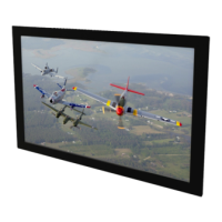
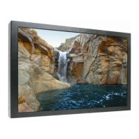
Touching the LCD with excessive force may leave pressure spots
that show in video display. Handle with care.
2. VIDEO INPUTS
The Rosen Remote Display System enables viewers to watch high-definition video as well as
standard-definition video. The 0700-104 remote electronics box supplies the following video
inputs.
Two 3G-SDI inputs
Two composite (CVBS)
Two DVI inputs (HDMI)
RGB & Component (YPbPr) - through the DVI connectors only
Accepts inputs up to 1080p, VGA-WUXGA
This unit can be controlled via an IR (infrared) remote interface, RS-232-based 7-button external
controller (P/N 0300-408), or RS-485 external inputs. The display connects to 28VDC aircraft
power and receives video through a video distribution amplifier or directly from video sources.
 Loading...