Rosen Aviation Remote Display System
Revision: A
Date: 04/24/12
Template: 4.2.3-6-FM; Revision A; 16 May, 2005
Outline and Installation drawings for the Rosen Remote Display System are available
on the Rosen website at www.rosenaviation.com.
Attach the 32” cosmetic back to the bulkhead using six #6 100 FHP screws
(customer supplied).
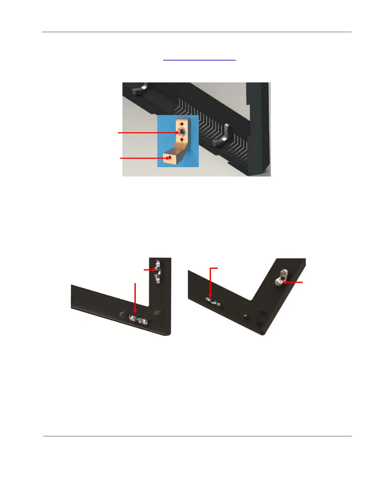
Figure 17 3201-800 cosmetic back mounting bracket
4.2. Mounting a Bezel
Mount the cosmetic back and monitor before attaching the bezel. To attach a bezel to an RDM,
align the mounting bosses with the monitor standoffs and gently press on the retaining clips to
snap the bezel into place.
Bezels attach around the perimeter of the RDMs with retention fasteners. The quantity and type
of bezel fasteners varies depending on the size of the bezel and RDM. Figure 18 shows the
different assembled retention fasteners on the bezels.
Figure 18 Different bezel retention fasteners
Ball stud
receivers on
32” bezel
sides
Only wire
retaining clips on
19”–26” bezels
Top and
bottom
wire clips
 Loading...