Rosen Aviation Remote Display System
Revision: A
Date: 04/24/12
Template: 4.2.3-6-FM; Revision A; 16 May, 2005
5. SYSTEM CONNECTIONS
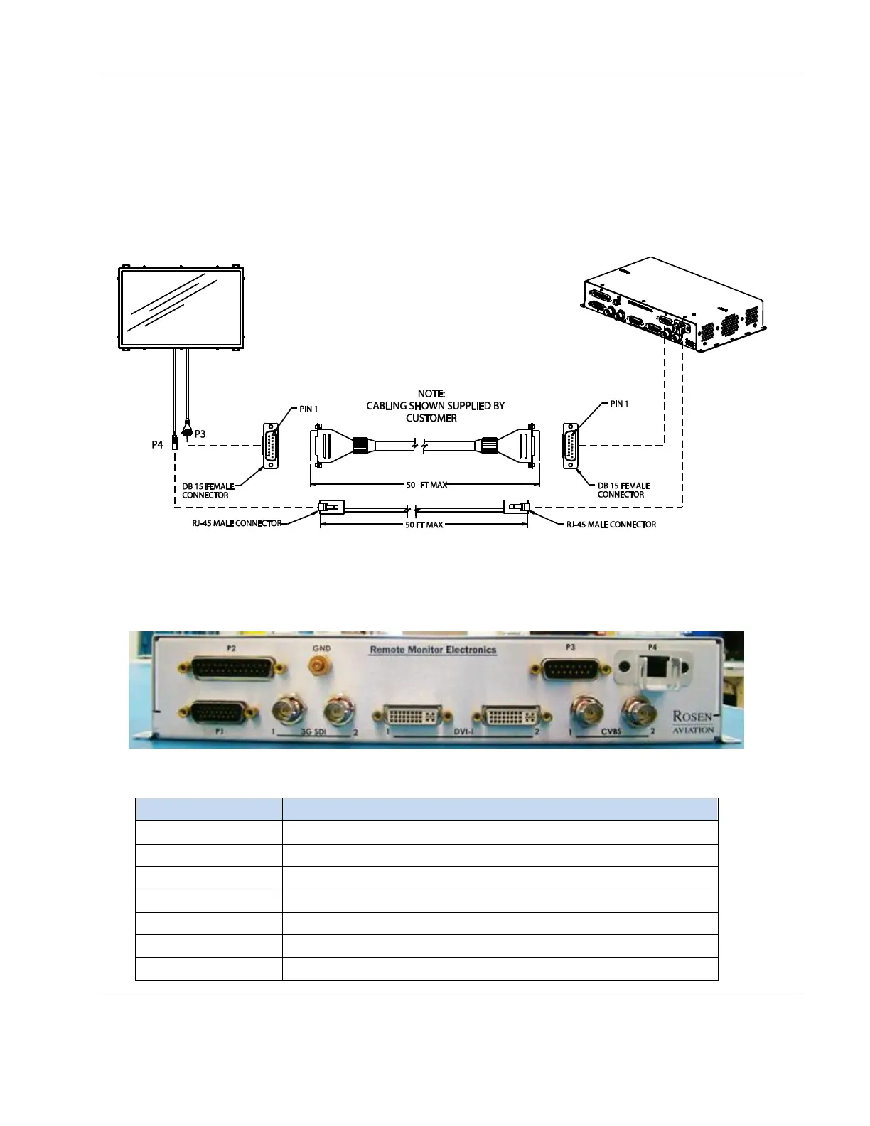
The RDM receives power, control, and serialized video from the RMEB located up to 50 feet away,
as shown below. The RMEB outputs a serialized video signal via an RJ-45 cable from P4 and
provides conditioned power and control to the RDM via a harness with DB15 connectors from P3.
We recommend using Siemon ZM6A-S(xx)-(xx) RJ45 cable up to 50 feet in length. If using an
alternate cable or multiple connections, please contact Rosen Aviation for additional information.
See the wiring tables on the Outline & Installation drawings for more details.
Figure 19 Remote display system connections
5.1. Remote Monitor Electronics Box Connectors
This section describes the 0700-104 RMEB connectors and the video inputs that are available.
Figure 20 RMEB connectors
Table 1 RMEB connectors and functions
Communication for RS-232, RS-485, External IR control
Conditioned power out to the monitor
Video signal out to the monitor
HDMI / DVI / Component / RGB video in
 Loading...