Rosen Aviation Remote Display System
Revision: A
Date: 04/24/12
Template: 4.2.3-6-FM; Revision A; 16 May, 2005
1.2.2. RMEB Connector Kits
The following connector kits (sold separately) are recommended:
Connector kit—26-pin female (P/N 0300-043)
Connector kit—25-pin female D-sub (P/N 0300-052)
CVBS and SDI connector kit—BNC (P/N 0300-051)
Component/RGB, digital HDMI/DVI connector kit—25-pin (P/N 0300-029)
1.2.3. Monitor Connector Kit
The remote monitors use the same connections regardless of the size:
RJ-45 Plug connector kit—(P/N 0300-050)
DB15 female connector kit—(P/N 0300-053)
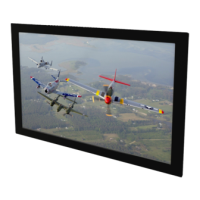
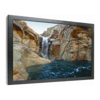
1.3. Mounting Configurations
The Rosen remote display monitors can be flush mounted, mounted with a sleek bezel, or
proud-mounted between a bezel and cosmetic back plate, as shown below. Please contact
Rosen Sales for bezel kit requirements.
Figure 1 Bulkhead mounting options for remote display modules
Flush mount – RDM only
Semi-proud mount –RDM with bezel (all sizes)
Proud mount – RDM with bezel and a cosmetic back plate
 Loading...